
Simple Proximity Detector & Alarm Circuit
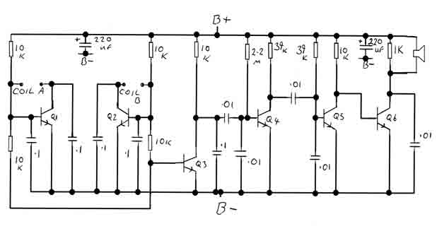
The proximity switch circuit based on the IC 4049 operates by utilizing the characteristics of an oscillator integrated with a resonant tank circuit. The tank circuit consists of an inductor (coil) and capacitors (C1 and C2), which are tuned to resonate at a specific frequency. The IC 4049's oscillator generates an alternating current (AC) signal that is influenced by the presence of nearby metallic objects.
When a metal object approaches the coil, it alters the electromagnetic field around the coil, thereby affecting the resonant frequency of the tank circuit. This interaction leads to a reduction in the voltage amplitude across the tank circuit. The oscillator's output is monitored through the feedback resistor connected to pins 2 and 5. As the voltage amplitude diminishes, the circuit's feedback mechanism responds by increasing the resistance. This adjustment effectively increases the detection range of the circuit.
The circuit can achieve a maximum detection range of approximately 1 inch when a high Q coil is employed, which is essential for maintaining sensitivity and accuracy in metal detection applications. To optimize the circuit for different detection distances, the values of the capacitors C1 and C2 can be adjusted. This tuning allows the user to set the circuit for specific operational distances, ensuring reliable detection of metal objects.
In summary, the IC 4049-based proximity switch circuit is a versatile solution for metal detection and proximity sensing, leveraging an oscillator and resonant tank circuit to provide adjustable and reliable performance. The careful selection of components and tuning of the circuit parameters are critical for achieving the desired detection range and sensitivity.This is a simple proximity switches with IC 4049th The IC4049 is a bipolar monolithic integrated circuit for use in metal-detection system / proximity sensing applications IC4049 includes an oscillator constituted by an external parallel resonant tank circuit and a feedback resistor connected 2-5 The internal oscillator operates near the resonant frequency of the tank is brought circuit. As a metal object near the coil begins to decrease the amplitude of the voltage across the tank gradually. If the envelope of the oscillation a certain level, the greater the resistance the greater the travel distance.
Detection-point range with a high Q coil. Maximum possible range can be achieved with a well extended to 1-inch drive circuit. Only So this circuit, the tuning circuit to a certain range. For making it easy to a metal coil at the desired distance (1 inch) square and adjust the resistance, C1 and C2 (make Pin2 or 5) one of the outputs in the state change. 🔗 External reference
Related Circuits
In many countries, it is now mandatory or at least recommended to have a rear fog light on a trailer, with the additional requirement that when the trailer is attached to the vehicle, the rear fog light of the...
When the water level is below the steel rods, there is no contact between the metal can and the rods, which are supported by a small insulated wooden board. The circuit built around IC1 draws no current, resulting in...
By adjusting the oscillators so their frequencies are very nearly the same, the difference between them is made audible as a beat note. This beat note changes slightly when the search loop is moved over or near to a...
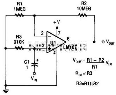
A general-purpose noninverting AC amplifier for audio and other low-frequency applications is presented. Design equations are included in the figure. Almost any general-purpose operational amplifier can be utilized for U1. The circuit configuration features a noninverting amplifier topology, which is widely...
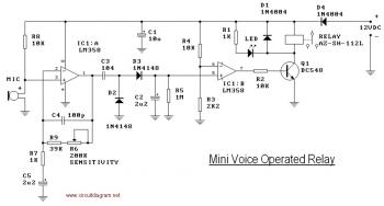
This circuit diagram illustrates a voice-operated relay, which functions similarly to a sound-activated switch circuit. It activates and deactivates the switch based on sound input. The output switch of this circuit is controlled by a relay. The release time...
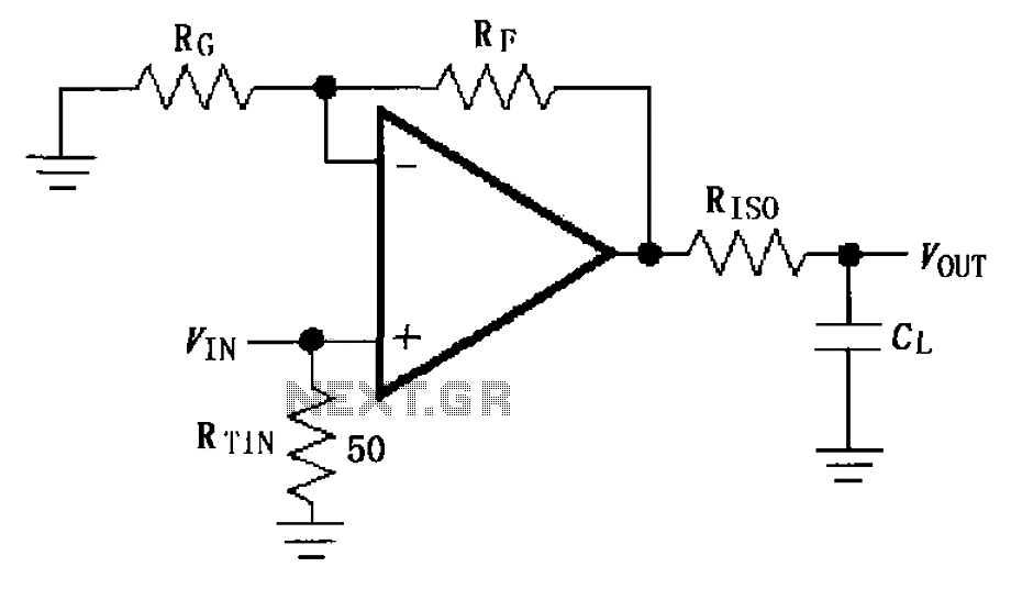
The circuit depicted in FIG demonstrates the MAX4450/4451 utilizing a capacitive load drive circuit with an isolation resistor (RISO). This configuration is situated between the output terminals and the load, along with an additional resistor, to mitigate overshoot and...
Warning: include(partials/cookie-banner.php): Failed to open stream: Permission denied in /var/www/html/nextgr/view-circuit.php on line 713
Warning: include(): Failed opening 'partials/cookie-banner.php' for inclusion (include_path='.:/usr/share/php') in /var/www/html/nextgr/view-circuit.php on line 713