
Alarm interface circuit

The alarm interface circuitry is designed to provide a visual indication of the operational status of multiple annealing furnaces. The two-color LED display serves as an effective means of communication, allowing operators to quickly assess the condition of each furnace. The green LED indicates that the furnace is operating within the normal temperature range, while the red LED signals that the temperature has exceeded the safe operating limit. The yellow LED serves as a warning that the temperature has fallen below the acceptable threshold, prompting the operator to take corrective action.
The control logic for the LED indicators is implemented using a combination of the C-8255A programmable peripheral interface and the 8031 microcontroller. The C-8255A, which provides multiple I/O ports, is configured to drive the LEDs based on the input signals LAi and LBi. The 8031 microcontroller is programmed to monitor these inputs and control the output to the LED display accordingly. This setup ensures that the display accurately reflects the status of each furnace in real-time, enhancing operational safety and efficiency.
In summary, the alarm interface circuitry effectively utilizes a two-color LED display to convey critical temperature information for multiple annealing furnaces, with control managed by dedicated microcontroller and peripheral interface components. This design promotes proactive monitoring and management of furnace operations, thereby reducing the risk of overheating and potential equipment failure.Alarm interface circuitry. As shown, the two-color light-emitting diode display. When LAi is high level t and LBi is low, the green light-emitting diode display; on the contrar y, LAi low + LBi is high, LED display red; if both are high, showing yellow. Each system LED indicates a furnace, the temperature is normal green, high in red was in yellow t fall below the upper limit value. Thus, the operator can at any time according to the color-color LED display, find out whether or not each block annealing furnace is working properly.
Display colors are controlled by the said C-8255A (PCO ~ PC7) and 8031 Pl port (P17 ~ P10) to complete.
Related Circuits
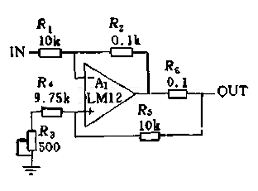
In a servo system, the current drive connection is frequently utilized. The output current (IOUT) is proportional to the input channel number (y). Using the current drive mode can mitigate issues caused by the motor's large inductance, which induces...
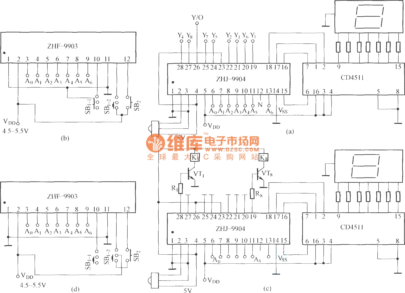
This is an eight-way signal remote control selection circuit composed of ZHJ-9904. It includes a remote control transmitter circuit, an eight-way switch control circuit, and a remote control transmitter. The eight-way signal remote control selection circuit utilizing the ZHJ-9904 is...
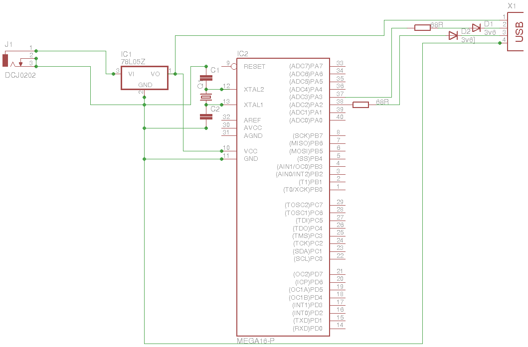
The 5 V from USB appears to be powering the LED on the laptop power brick. Therefore, even when the power brick is turned off at the wall outlet, the LED remains illuminated. When the USB is unplugged, the...
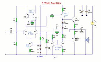
The diagram illustrates a 5W audio amplifier circuit constructed using power transistors BD139 and BD140 for the final amplification stage. This compact amplifier serves as a general-purpose amplifier suitable for applications such as computer audio, radio, MP3 players, and...
The motors will be powered by the full source voltage, so it is important to ensure that this does not cause the robot to operate too quickly. The Firebot utilizes GM3 motors powered by a 9V battery; however, in...
Free domains and hosting with up to 1GB of disk space, unlimited transfer, and access to PHP as well as 5 MySQL databases. The maximum size of a single file is not limited. This service offers a robust web hosting...