
Line Following Robot circuit
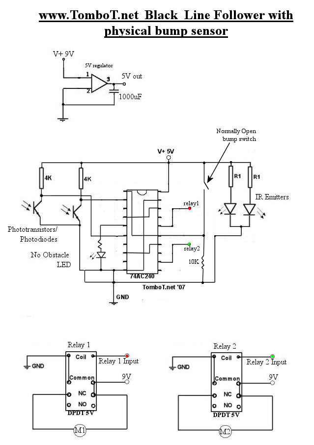
The described circuit operates a robotic system utilizing GM3 motors, which are typically rated for higher voltages but are limited to 5V in this configuration to manage speed and control. The power supply is critical, as the motors must be driven at a controlled voltage to prevent excessive speed that could compromise maneuverability and safety.
The line-following capability of the robot is facilitated through the use of line detectors that communicate with relay switches. These relays toggle based on the input status from the detectors, allowing for precise control of motor direction. Specifically, the left line detector is configured to activate the right motor, while the right line detector activates the left motor. This cross-activation is essential for maintaining the robot's trajectory along a designated path.
Moreover, the obstacle detection system plays a significant role in enhancing the robot's operational capabilities. By utilizing a dedicated set of inputs on the line-following chip, the circuit can dynamically enable or disable functionalities based on the presence of obstacles. The second set of inverters, which are continuously grounded, ensures that the obstacle detection mechanism is always active, allowing for real-time adjustments to the robot's navigation strategy.
This design emphasizes the importance of voltage regulation, motor control, and sensor integration in creating an effective and responsive robotic system. Proper attention to these elements ensures that the robot can navigate its environment effectively while adhering to safety constraints.The motors will be driven from the full source voltage, so make sure this isn`t going to make your robot too fast! Firebot has GM3 motors driven with a 9V battery, however the circuit differed and the motors were only driven by 5V from the voltage regulator.
The line detectors drive the relays on or off dependant upon their status, remember that t he left line detector should drive the right motor and vice versa. The obstacle detector enables/disables the inputs on the line following chip. This is made possible by the fact that the chip has two sets of inputs, both with their own enables. The obstacle detector uses the second set of invereters which is grounded (enabled) constantly. 🔗 External reference
Related Circuits
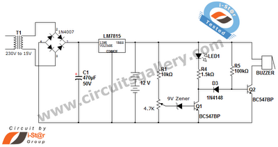
This is a straightforward 12V rechargeable smart battery charger circuit. It can be utilized as a charger for car batteries, inverter batteries, emergency light batteries, and more. An automatic indicator alarm circuit accompanies this battery charger schematic. The primary...

The amplifier circuit presented in this paper introduces a floating power supply aimed at increasing output power. The output power of the amplifier is influenced primarily by the final stage amplifier supply voltage. The circuit's principle is illustrated in...
LBl690 is a three-phase brushless DC motor drive control integrated circuit manufactured by Sanyo, a Japanese company. It is extensively utilized in both domestic and imported applications for broken wind and fresh air conditioning systems that require brushless DC drive...
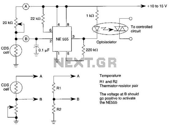
This dark-activated relay switch can be utilized to activate walkway or other outdoor lighting at dusk. By employing alternate connections to points A and B, it is capable of sensing varying levels of illumination, as well as high and...

Digital Command Control (DCC) provides significant advantages over traditional DC analog control systems, primarily due to its simplified wiring. DCC enables the individual control of multiple locomotives on the layout without requiring electrical isolation of track sections. The main...
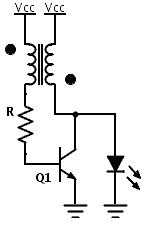
Previously, a boost circuit was tested that enables the powering of a 3 V LED using a discharged battery (approximately 1 V or lower). This circuit consists of a single transistor, one resistor, and a small transformer with a...