
Alarm LED Light Circuit
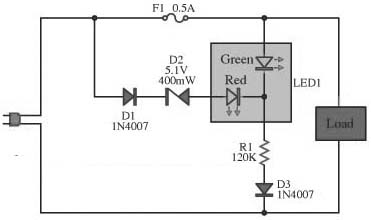
This circuit is an essential component for equipment monitoring, providing visual feedback through a dual-color LED indicator. The design incorporates a common cathode LED configuration, which simplifies the wiring and allows for clear visibility of the operational status. The use of a resistor (R1) to limit current ensures the longevity of the LED, preventing excessive current that could lead to failure. The choice of a zener diode in the circuit is critical, as it regulates the voltage across the LEDs, ensuring that only one LED lights up at a time, thereby avoiding confusion regarding the circuit's status.
In practical applications, the circuit can be used in various electronic devices where monitoring of operational integrity is necessary. The red LED serves as a warning indicator for a blown fuse, prompting the user to take corrective action. The green LED, on the other hand, signifies normal operation. The inclusion of diodes D3 and D4 enhances the reliability of the circuit by protecting the LED from potential damage caused by reverse polarity, particularly in AC applications. This design makes the circuit versatile and suitable for both AC and DC powered devices, ensuring functionality across a range of situations.This circuit yearn for act the performance of the equipment, otherwise Check the fuse here the circuit. The circuit is diminutive and the power supply voltage of all kinds. It demonstrate with LED, 2-color in individual. Which is cathode universal kind, the anode has two separate terminals. If the circuit is functioning well LED, it revealed in wet be hind the ears colour. The display is red, as the fuse into the circuit is damaged. The resistor R1 limits the current to gush through the LED is roughly 2 mA. This is an adequate amount to produce the LED light. If it lowers the R1 down, the LED light up. In the conventional setup of the circuit and The fuse is not damaged. The zener diode to prevent the green and red LED illumination up in chorus. Zener diode prevents the LED is simple and red illumination all together. The piercing efficiency LED, as soon as connected trendy like. The red LED uses high-pressure, so with the intention of single green LED illumination up only. Diodes D3 and D4 wish prevent dodgy instead of the LED. While the semi cycle downbeat voltage of the alternating current voltage. However, if the DC supply voltage. I act not retain to manage diode protection. 🔗 External reference
Related Circuits
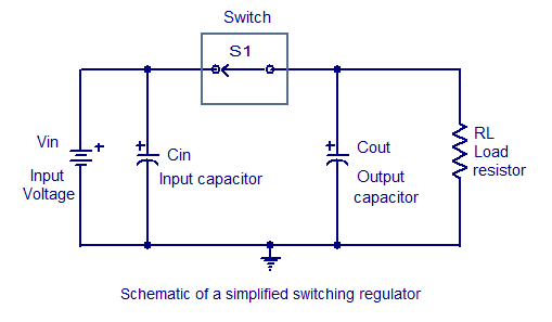
Switching regulators operate by drawing small amounts of energy from the input source and transferring it incrementally to the output. This is achieved using an electronic switch, which functions at a predetermined frequency, acting as a gate between the...
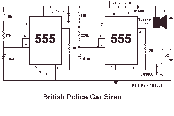
This month I am making 3 different types of siren circuits based on the 555 timer. The first circuit simulates the siren of a British police car. It uses two 555 timers in the circuit. The 555 on the...
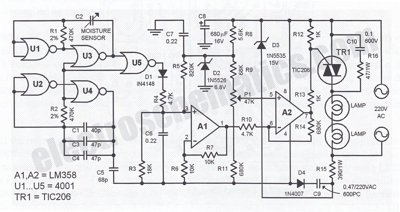
This humidity-controlled switch circuit activates and deactivates an electrical load, such as a heater, based on the moisture content in the surrounding air. The humidity-controlled switch circuit employs a humidity sensor to detect changes in moisture levels in the environment....
The electrical wiring diagram for the 1993 VW Passat includes the Engine Control Module, Automatic Control Unit, and Automatic Solenoid. This diagram illustrates the connections and wiring between various components of the vehicle's system, such as the multi-function switch,...

This is a circuit known as a Wien bridge oscillator. The circuit features both positive and negative feedback loops and operates under the control of an operational amplifier (op-amp). The oscillation frequency is determined by the RC time constant,...
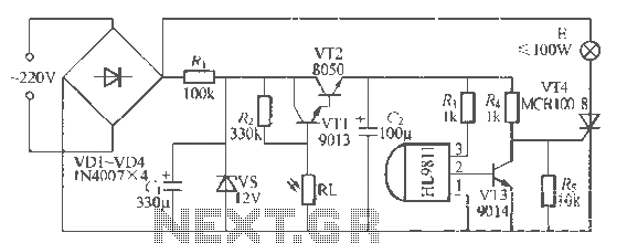
The H1.9811 single-channel flash control integrated circuit from Wuxi Love Core Microelectronics Co., Ltd. is designed for controlling flashing warning lights in road barricades. It features an integrated internal RC oscillator, frequency divider, output buffer amplifier, shaping circuit, and...
Warning: include(partials/cookie-banner.php): Failed to open stream: Permission denied in /var/www/html/nextgr/view-circuit.php on line 713
Warning: include(): Failed opening 'partials/cookie-banner.php' for inclusion (include_path='.:/usr/share/php') in /var/www/html/nextgr/view-circuit.php on line 713