
Wien Bridge Oscillator Circuit

The Wien bridge oscillator is a type of electronic oscillator that generates sine waves. It utilizes a combination of resistors and capacitors to create a feedback network that establishes the frequency of oscillation. The circuit typically consists of an op-amp configured in a non-inverting amplifier configuration, where the gain is controlled by the resistive elements in the feedback loop.
The key components of the Wien bridge oscillator include two resistors (R1 and R2) and two capacitors (C1 and C2) arranged in a bridge configuration. The resistors and capacitors are selected to set the desired frequency of oscillation, which can be calculated using the formula:
f = 1 / (2πRC)
where R is the resistance and C is the capacitance in the feedback network. The op-amp amplifies the signal, and the feedback loop ensures that the output oscillates at the calculated frequency.
To maintain stable oscillation, the circuit requires a method for automatically adjusting the gain of the op-amp. This is often accomplished using a thermistor or a light-dependent resistor (LDR) in conjunction with a variable resistor to provide the necessary gain control. This automatic gain adjustment helps to stabilize the amplitude of the output signal and prevents distortion in the waveform.
The output of the Wien bridge oscillator is a clean sinusoidal waveform, making it suitable for various applications, including audio signal generation, function generators, and testing equipment. The use of a rail-to-rail op-amp enhances the performance of the circuit by allowing the output voltage to swing close to the supply rails, maximizing the usable output range. The Wien bridge oscillator is valued for its simplicity, stability, and effectiveness in producing high-quality sine wave signals.This is a circuit that is known as wien bridge oscillator circuit. The circuit has positive and negative feedback loop. This circuit is work with control by op amp. This is the figure of the circuit. The circuit oscillates at a frequency determined by the RC time constant at frequency and produces a sinusoidal waveform at the output voltage Vout. In many cases this circuit is used as sine wave generator which is using rail to rail op amp. [Schematic`s diagram source: Advanced Linear Devices, Inc] 🔗 External reference
Related Circuits
The schematic below illustrates the division of a crystal oscillator signal by the crystal frequency to obtain an accurate 1-second time base with a precision of 0.01%. Two cascaded 12-stage counters (CD4040) form a 24-stage binary counter, and the...

This circuit is a touch switch circuit, similar to a touch door alarm. It utilizes a 555 timer as the core component of the touch switch circuit. The operation begins when the plate is touched, triggering the 555 timer....
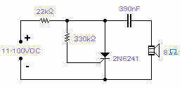
Silicon controlled rectifiers (SCR) can easily oscillate if there is an inductor (a speaker coil in this case) which gives just enough extra voltage to completely switch off the sustain current. In this way a new cycle may start...
The TBA120 Series integrated circuits (ICs) offer a high-gain limiting intermediate frequency (IF) amplifier and a quadrature coincidence detector in a single package. These ICs are primarily designed for the extraction of television intercarrier sound, which is frequency modulated...
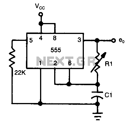
The frequency of oscillation depends on the Rl/Cl time constant, allowing for frequency adjustment by varying Rl. This is a basic circuit. The described circuit operates based on the relationship between resistance (Rl) and capacitance (Cl), which together form a...
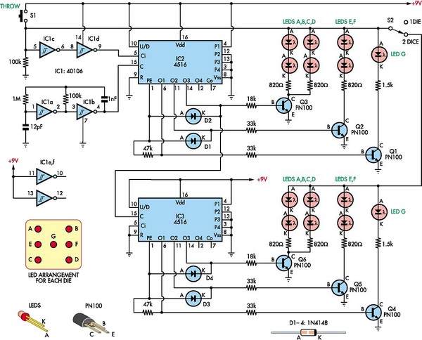
This circuit utilizes two 4516 integrated circuits (ICs) to simulate a game involving two dice. A switch is included to select whether one or two dice will be activated with each press. A 9-volt battery is sufficient for power...
Warning: include(partials/cookie-banner.php): Failed to open stream: Permission denied in /var/www/html/nextgr/view-circuit.php on line 713
Warning: include(): Failed opening 'partials/cookie-banner.php' for inclusion (include_path='.:/usr/share/php') in /var/www/html/nextgr/view-circuit.php on line 713