
VW CAR PASSAT ENGINE CONTROL AND AUTOMATIC SOLENOID ELECTRICAL WIRING CIRCUIT
The electrical wiring diagram for the 1993 VW Passat serves as a crucial reference for understanding the interactions between various components within the vehicle's engine management and automatic transmission systems. The Engine Control Module (ECM) is the central unit that processes inputs from various sensors, such as the coolant temperature sensor and throttle position sensor, to regulate engine performance and efficiency. The Automatic Control Unit (ACU) manages the automatic transmission's shift points and overall operation, relying on feedback from the shift lock solenoid and other related components.
Connections illustrated in the diagram include a multi-function switch that allows the driver to control multiple functions, such as lighting and wipers, while the fuse relay panel provides protection against overloads and short circuits in the electrical system. The knock sensor plays a critical role in detecting engine knock, enabling the ECM to adjust ignition timing for optimal performance.
The throttle valve potentiometer and idle air control valve are essential for maintaining engine idle speed and responsiveness to throttle inputs. The inclusion of the ignition booster ensures that the ignition system operates efficiently, providing a reliable spark for combustion. Furthermore, the diagram outlines the routing of wiring for the carbon canister and evap emission on/off valve, which are vital for controlling emissions and maintaining compliance with environmental regulations.
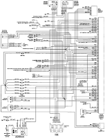
In summary, this wiring diagram is an indispensable tool for technicians and engineers working on the 1993 VW Passat, offering a comprehensive view of the electrical connections and functional relationships between critical engine and transmission components. Proper understanding and utilization of this diagram facilitate effective troubleshooting, maintenance, and repair of the vehicle's electrical systems.1993 VW Passat Engine Control Module, Automatic Control Unit, and Automatic Solenoid Electrical Wiring Diagram are shown in the following figure. It shows the connection and wiring between each parts and component of Engine Control Module, Automatic Control Unit, and Automatic Solenoid system of the vehicle such as the multi-function switch, fuse/
relay panel, knock sensor, coolant temperature sensor, shift lock solenoid, starter interlock/back up lit relay, automatic control computer clutch shut off relay, automatic control unit, automatic solenoids, program switch, throttle position sensor, full throttle switch, idle switch, throttle valve potentiometer, ignition booster, distributor firing order, engine control module, carbon canister, cold starter, idle air control valve, evap emission on/off valve, and many more. 🔗 External reference
Related Circuits
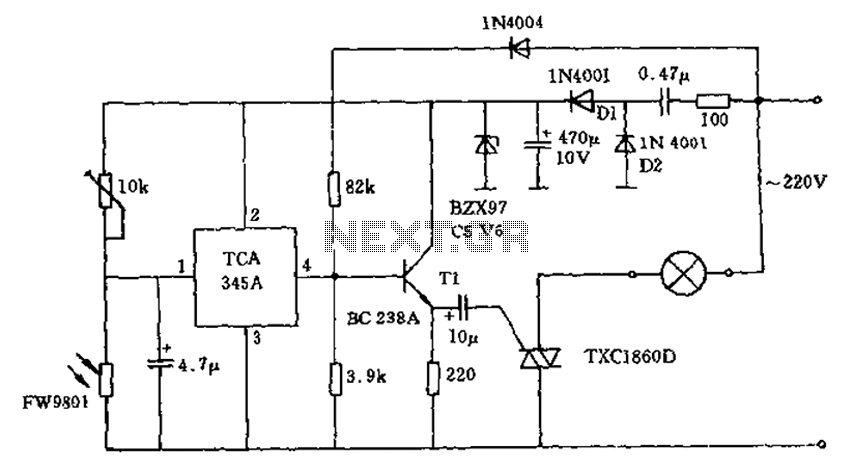
A 200W lamp switch control operates at a power supply voltage of 220V. It automatically turns the light on or off based on ambient illumination levels, specifically activating at approximately 100 lux. In low light conditions, a time-sensitive resistor...
Here is an updated schematic featuring the RF Solutions receiver along with several minor additions. The design includes additional circuitry to manage the signals effectively. The updated schematic incorporates an RF Solutions receiver, which is essential for receiving radio frequency...
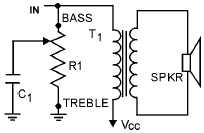
An audio tone control integrates both bass and treble controls within a single circuit. Such tone controls are typically found in lower-end audio equipment, as they conserve front panel space and require only one control knob instead of two...
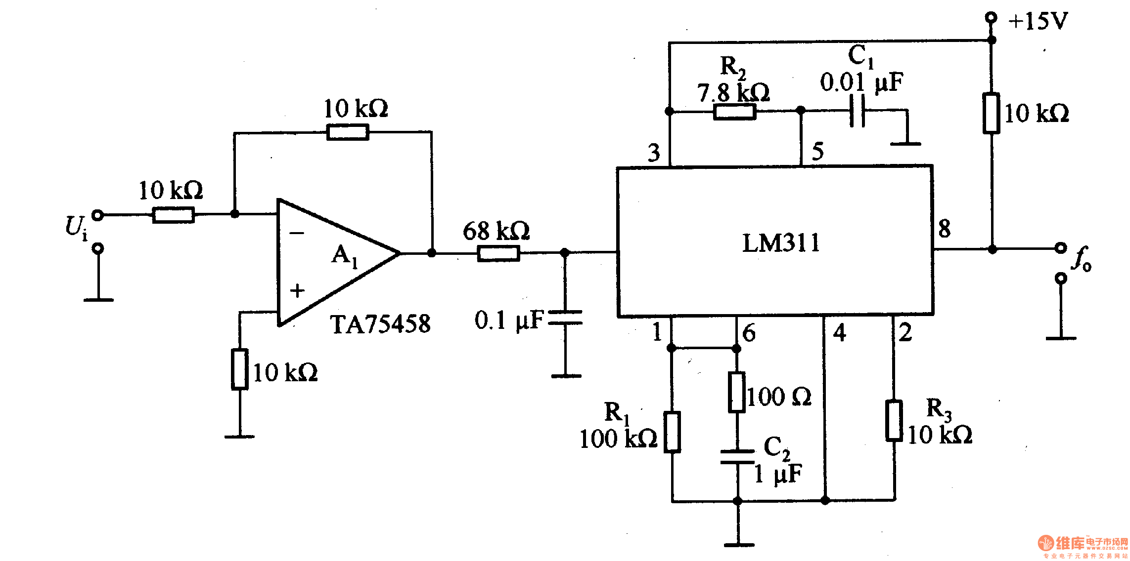
The LM311 is an integrated circuit that functions as a reference voltage generator, comparator, amplifier, and discharge circuit. It is designed for ease of use. In the circuit, the output frequency f0 is... The LM311 is a versatile integrated circuit...
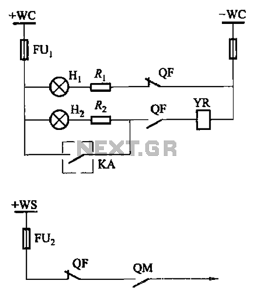
The CS2 type is a manually operated breaker mechanism commonly utilized for AC power operation and manual control signal circuits, as depicted in Figure 6-68. The circuit includes various components: wc for small signal bus control, QF for auxiliary...

The interface circuit is placed between the computer's standard video signal output terminal and the television. It amplifies the standard 1V (Peak-to-Peak) video signal to 3V (Peak-to-Peak). The negative feedback circuit consists of transistors T1 and T2, providing a...
Warning: include(partials/cookie-banner.php): Failed to open stream: Permission denied in /var/www/html/nextgr/view-circuit.php on line 713
Warning: include(): Failed opening 'partials/cookie-banner.php' for inclusion (include_path='.:/usr/share/php') in /var/www/html/nextgr/view-circuit.php on line 713