
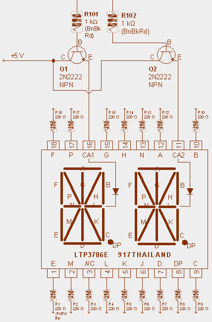
ALPHANUMERIC LED DISPLAY PROJECT
The described circuit involves a motor system equipped with a visual indicator, referred to as a "tiny sandwich flag," which serves to measure the rotational speed of the motor spindle. The flag's perpendicular orientation to the spindle facilitates clear visibility of its movement during operation. Initially, the motor's performance was limited, with each electrical pulse from a capacitor causing the flag to rotate only a quarter of a full rotation. This behavior indicates a low-energy output from the capacitor, suggesting that the motor was operating at a low efficiency level.
As the design evolved, enhancements were made to the circuit, particularly through the implementation of larger capacitor values. This modification significantly increased the energy delivered to the motor, resulting in a dramatic rise in rotational speed, surpassing the ability of a human observer to count the rotations accurately. The transition to more powerful capacitors suggests a shift towards optimizing the motor's operational parameters, likely improving the overall response time and performance characteristics of the system.
To facilitate manual testing of the motor's performance, a pushbutton switch (SW1) was incorporated into the circuit. This switch allows for the manual triggering of the motor, enabling the user to observe the effects of varying capacitor values on the rotational speed directly. Additionally, there is mention of an infrared interrupter pair, which is intended for future integration into the circuit. This component would automate the counting process by detecting the passage of the flag through a predetermined point, thereby providing a more precise and efficient means of measuring the motor's rotational speed. The connection of this infrared system to the BEAM engine project indicates a broader application of the circuit design, potentially extending its utility to other robotic or automation projects.
Overall, the evolution of this motor control circuit demonstrates a clear progression from basic manual operation to a more sophisticated automated measurement system, highlighting the importance of component selection and circuit design in achieving desired performance outcomes.A tiny sandwich flag connected perpendicular to the motor spindle aids observation of how long it takes to complete one full rotation. This worked initially, as each burst from the capacitor barely moved the flag 1/4 of a rotation. As the circuit variations became more efficient and powerful (the capacitors values became larger), a single burst provided rotational speed faster than a human can count.
I took a huge diversion and built a counter circuit. A pushbutton (SW1) was necessary for manual testing, although an infrared interrupter pair would eventually provide input when connected to the BEAM engine project. 🔗 External reference
Related Circuits
This audio noise filter circuit is a bandpass filter designed for the audio frequency range. It effectively filters out unwanted signals that fall outside the audio frequencies. The circuit consists of two filters: a low-pass filter and a high-pass...
An array of white LEDs can serve as an effective small lamp for the living room. LED lamps are commercially available. LED arrays are increasingly popular for providing ambient lighting in residential spaces. The use of white LEDs in a...

The RCA-83 rectifier utilizes 5VAC for the filament supply. The heaters for the 5687 tubes are powered by a full bridge rectifier consisting of MUR860 diodes, followed by five 10,000µF Elna capacitors. Current regulation is achieved through an LM317...
Flyback LED drivers are versatile as they can be utilized in applications with input voltages either above or below the necessary output voltages. They feature a straightforward circuit configuration that maintains a constant LED current without the need for...
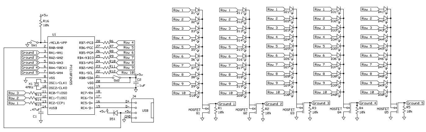
To control 40 LEDs using a single PIC 18F2455 microcontroller, the LEDs were organized into a configuration of four columns, each containing 10 rows of LEDs. Each LED in a column was connected to a separate pin on the...
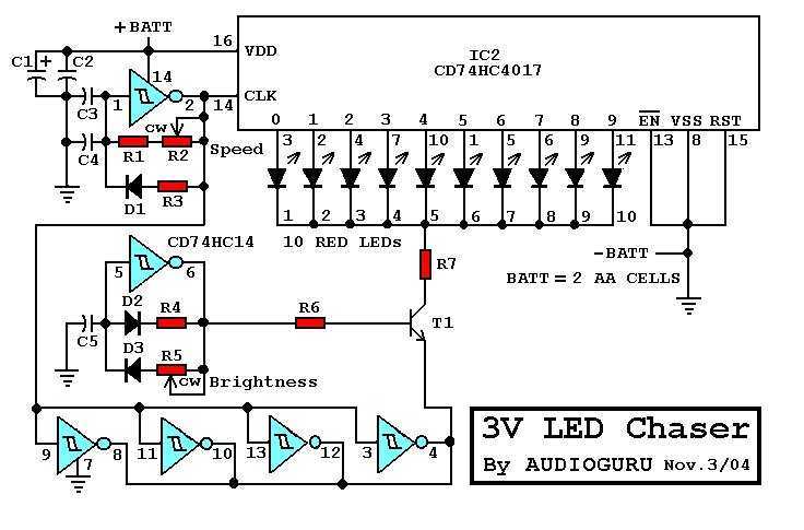
There are many 9V chaser circuits that seem to waste about 7V when driving LEDs that are only about 2V. This project is unique, because it uses only two inexpensive alkaline battery cells totaling 3V for power. Since most...
Warning: include(partials/cookie-banner.php): Failed to open stream: Permission denied in /var/www/html/nextgr/view-circuit.php on line 713
Warning: include(): Failed opening 'partials/cookie-banner.php' for inclusion (include_path='.:/usr/share/php') in /var/www/html/nextgr/view-circuit.php on line 713