
LED control system for 40 LEDs using a single PIC
To synchronize the display for persistence of vision, the PIC must track the time between successive rotations. Various magnetic sensors were evaluated for this purpose. Ultimately, a reed switch and magnet were selected for timing control, replacing an initially considered Hall effect sensor. The Hall effect sensor exhibited excessive sensitivity to the magnet, resulting in noise and an oscillating signal when observed on an oscilloscope. In contrast, the reed switch, while slower, provided a smooth and stable signal without noise. However, contact bounce issues were encountered, which affected the switch's performance. The magnet was affixed to an L-connector on one side of the mechanical system, while the reed switch was soldered onto the PCB. This arrangement ensured that the switch passed beneath the magnet with each rotation. When the magnet is positioned above the reed switch, the internal leads of the switch connect, allowing voltage to briefly flow to port RB0 on the PIC.
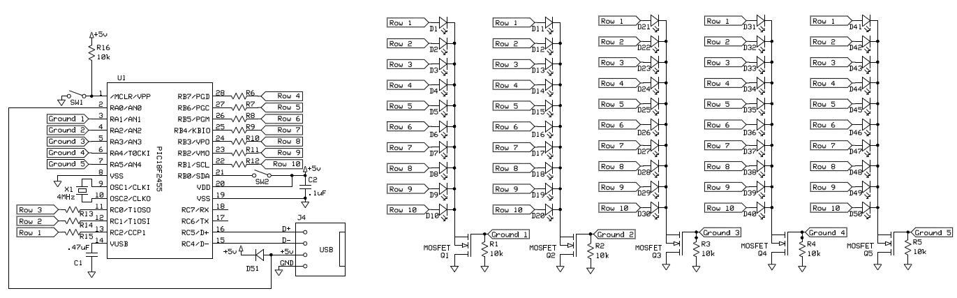
The circuit design effectively utilizes a multiplexing technique to control the 40 LEDs, allowing for a significant reduction in the number of required microcontroller pins. The n-type MOSFET serves as a low-side switch for each column, enabling the microcontroller to ground the LEDs selectively. This setup minimizes power consumption and allows for dynamic control of the LED display.
The reed switch, chosen for its reliability over the Hall effect sensor, simplifies the timing mechanism. The physical arrangement ensures that the reed switch is activated precisely once per rotation of the mechanical system, which is critical for maintaining the correct timing of the LED display. The design also addresses potential contact bounce by ensuring that the mechanical movement is smooth and consistent, which is essential for accurate timing and display performance.
In summary, the circuit effectively combines LED control through multiplexing, reliable timing using a reed switch, and careful design considerations to mitigate issues such as noise and contact bounce, resulting in a functional and visually appealing LED display system.In order to control 40 LEDs with a single PIC 18F2455 microcontroller, we broke the LEDs into a system of four columns containing 10 LED rows. Each of the 10 LEDs in a column was connected to a pin on the PIC. The grounds of all LEDs in a column were connected, with ground controlled by a n-type MOSFET transistor.
Only when the input to the transistor was set high was a given column of LEDs grounded; we were able to achieve the semblance of a constant display by quickly cycling between which LED posts are controlled.
In order to time the display properly to achieve persistence of vision, the PIC needs to record the time between successive rotations. To do this in our project, we investigated various magnetic sensors. In the end, we decided to control timing with a reed switch and magnet (we were originally using a Hall effect sensor). The Hall effect sensor was so sensitive to the magnet that it was susceptible to noise and showed an oscillating signal when we measured it with an oscilloscope. The reed switch is slower, so the signal was smooth and without noise.
Nevertheless, we encountered issues potentially due to contact bounce which interfered with the performance of the switch. We put the magnet onto an L-connector on one side of the mechanical system and soldered the reed switch onto the PCB so that once every rotation it passed underneath the magnet. When the magnet is above the reed switch, the two leads inside it connect, and voltage can briefly pass through the switch to port RB0 on the PIC.
🔗 External reference
Related Circuits
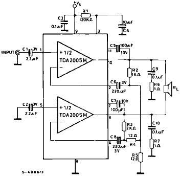
The TDA2005 is a Class B dual audio power amplifier package specifically designed for car radio applications. It facilitates the easy design of car radio power boosters. The TDA2005 power amplifier is engineered to deliver high-quality audio output in automotive...
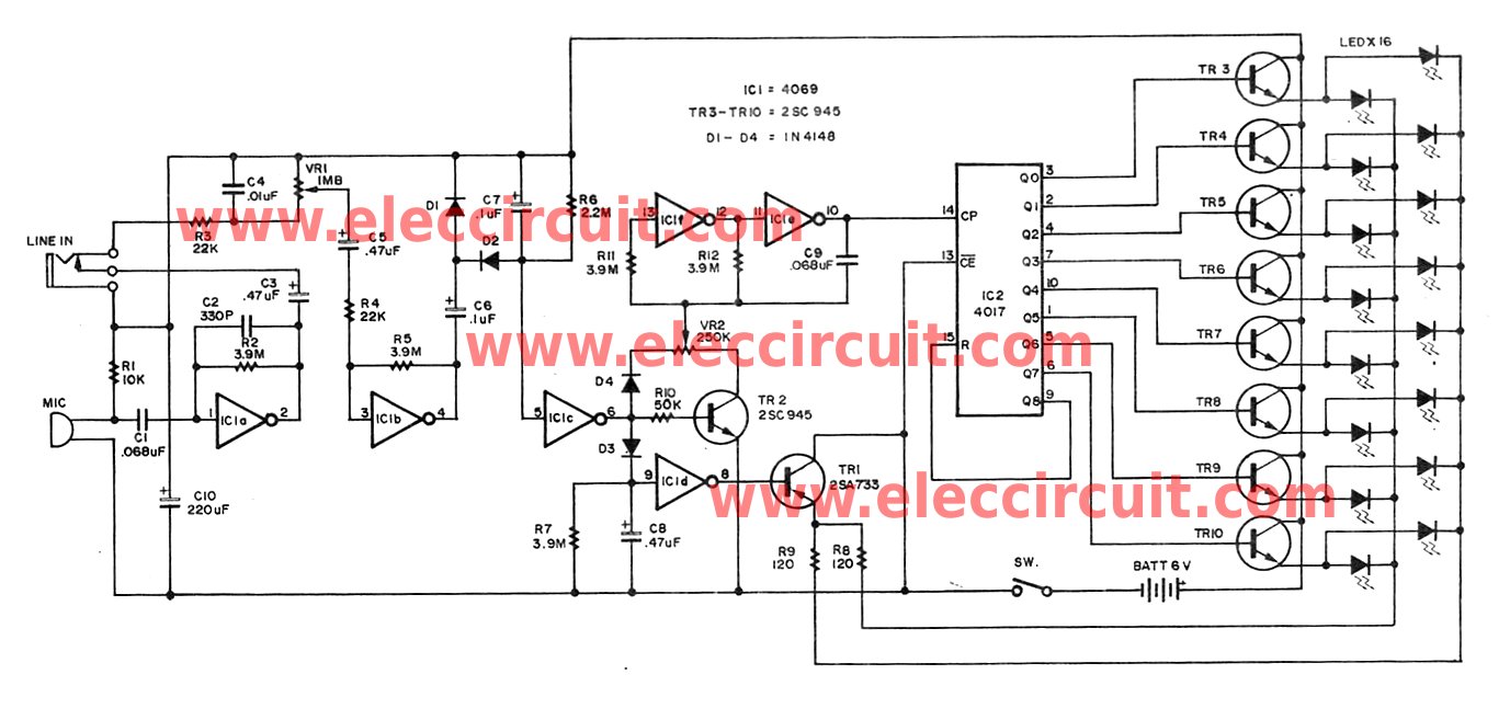
This circuit is designed for children's entertainment and can be installed on bicycles, battery-powered cars, motorcycles, as well as on models and various games and toys. When switch SW1 is positioned as depicted in the circuit diagram, it generates...
Individuals seeking a distinctive gift for Christmas and New Year may find this project appealing. Certification of this project will undoubtedly create a preference for it. The project in question appears to be a creative endeavor aimed at providing a...
The liquid level controller circuit comprises a power supply circuit and a level detection control circuit, as illustrated in the accompanying chart. The power supply circuit includes a power switch (S1), a power transformer (T), bridge rectifiers (UR1, UR2),...
Most homes today have at least a few infrared remote controls, whether for the television, video recorder, stereo, etc. Despite this, many have experienced frustration when the light remains on after settling into a comfortable chair to watch a...
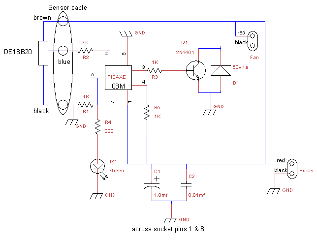
This is a fan controller designed for an audio/video cabinet. It utilizes a PICAXE 08M microcontroller and a DS18B20 temperature sensor. The fan activates at 30 degrees Celsius (approximately 86 degrees Fahrenheit) and deactivates at 28 degrees Celsius (around...
Warning: include(partials/cookie-banner.php): Failed to open stream: Permission denied in /var/www/html/nextgr/view-circuit.php on line 713
Warning: include(): Failed opening 'partials/cookie-banner.php' for inclusion (include_path='.:/usr/share/php') in /var/www/html/nextgr/view-circuit.php on line 713