
3V LED Chaser
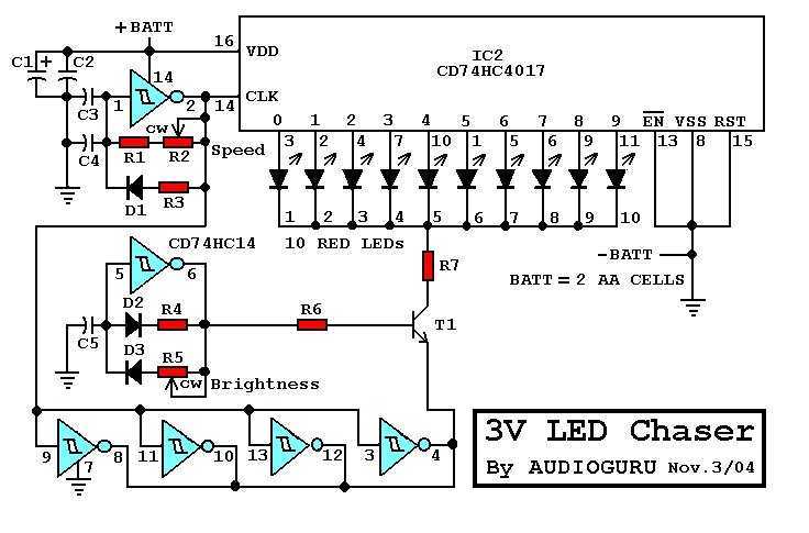
This circuit design employs a minimalistic approach to LED chaser functionality, leveraging a 3V power supply derived from two alkaline battery cells. The reduction in voltage waste is a significant improvement over traditional 9V chaser circuits, which often leave a substantial portion of the voltage unused, leading to inefficient power consumption and reduced battery life.
The core of the circuit consists of a microcontroller or a simple timer IC, which governs the timing of the LED activation. The circuit is designed to flash each LED for a brief duration of approximately 30 milliseconds. This short activation time not only enhances the visual effect of the LEDs appearing to "chase" each other but also minimizes power consumption, contributing to the extended battery life.
To facilitate user interaction, the circuit includes a stepper speed control, allowing the user to adjust the rate at which the LEDs activate in sequence. This can be achieved using a potentiometer that alters the frequency of the timing signal, effectively controlling how quickly the LEDs light up one after the other. Additionally, a brightness control feature is integrated, typically using a PWM (Pulse Width Modulation) technique. By varying the duty cycle of the PWM signal, the perceived brightness of the LEDs can be adjusted, further optimizing power usage.
The physical arrangement of the LEDs is crucial for achieving the desired chaser effect. By mounting the LEDs in a circular configuration, the visual output creates an illusion of movement as the LEDs light up sequentially. This layout not only enhances aesthetic appeal but also maximizes the visibility of the chaser effect.
Overall, this LED chaser circuit exemplifies an efficient design that balances performance with power conservation, making it suitable for applications where battery life is a critical factor.There are many 9V chaser circuits that seem to waste about 7V when driving LEDs that are only about 2V. This project is unique, because it uses only two inexpensive alkaline battery cells totaling 3V for power.
Since most of the waste is eliminated, the cells last a long time. Unlike the other circuits, this one flashes the LEDs for only about 30ms each, further extending the battery life. For user convenience, it has a stepper speed control and a brightness control. At slower speeds and with reduced brightness, the battery life is further extended considerably. Mounted in a circle, the LEDs appear to rotate as they step from one to the next. 🔗 External reference
Related Circuits
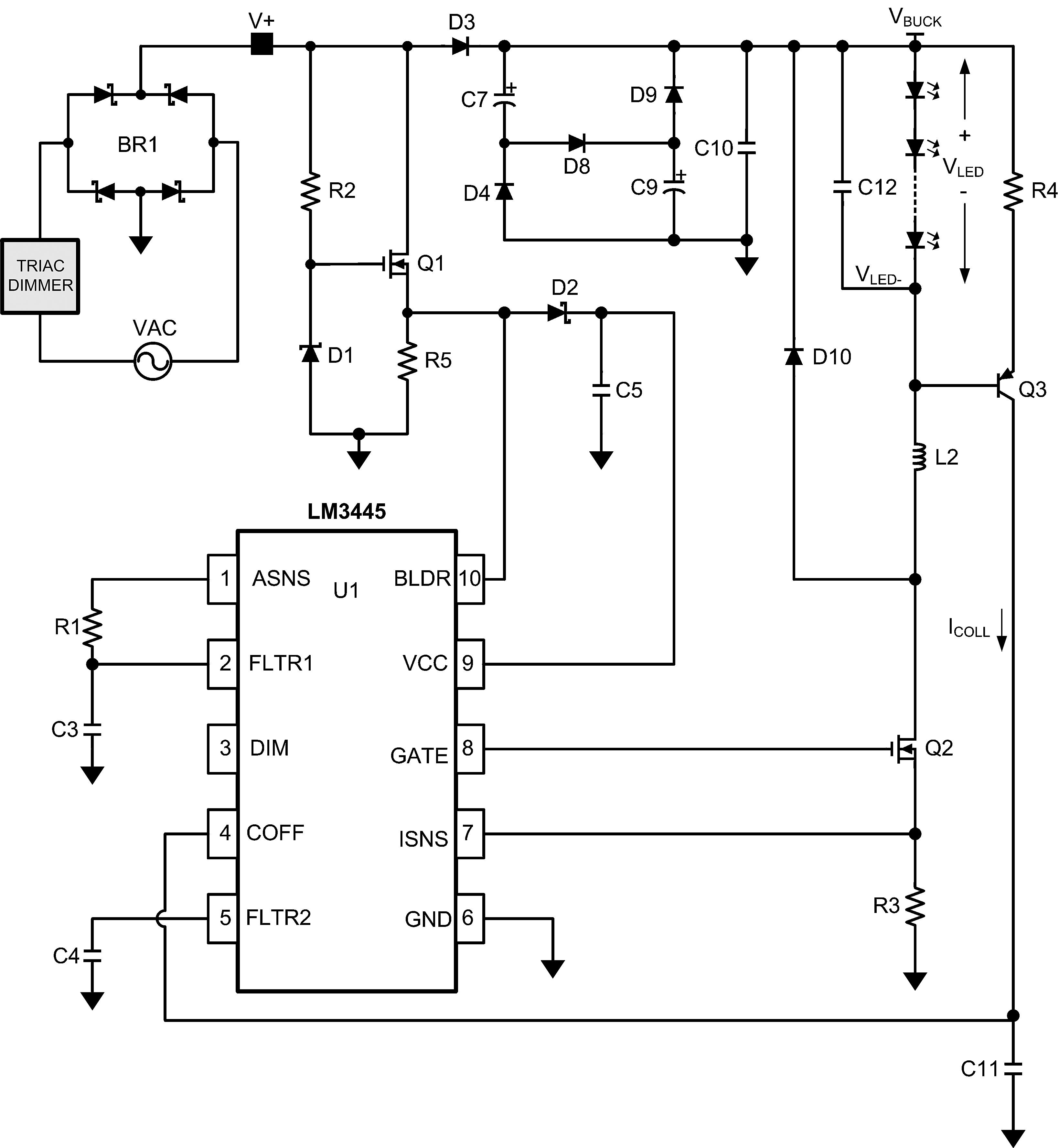
The LM3445 is an adaptive constant off-time AC/DC buck (step-down) constant current controller designed for compatibility with triac dimmers. The LM3445 is a specialized integrated circuit that functions as a constant current controller in AC/DC applications, particularly suited for LED...
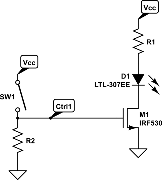
A 4-position slide switch is utilized to activate different colored LEDs based on its position. Additionally, it is required to adjust the output frequency of a 555 timer operating in astable mode to drive a piezo buzzer. The challenge...
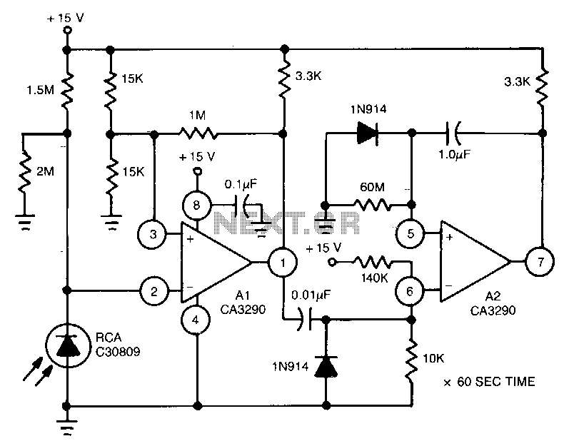
This circuit utilizes the CA3290 BiMOS dual voltage comparator to detect variations in the current of a light-emitting diode (LED). The output from the comparator triggers A2, a one-shot timer. If the light source to the photodiode is disrupted,...

This circuit is designed for general-purpose use with a large LED display utilizing SPI serial interfacing. It employs a serial-in-parallel-out shift register, specifically the 74HC595, to receive serial data from a microcontroller board. The schematic wiring indicates that SER...

Using only 2 capacitors, 3 resistors, 4 seven-segment displays, 1 xtal, 2 switches n.o. and 1 Microcontroller PIC, you can build this Digital Led Clock. You can use common anode or common cathode display, just select the display type....
This document presents the circuit diagram of an IC-controlled emergency light with a charger, which functions as a 12V to 220V AC inverter circuit. The primary features of this circuit include automatic activation of the light during mains failure...