
Alternate Tone Alarm Circuit

The output at pin 10 of IC2 is connected to IC4, the CD4027, which is a dual J-K master-slave flip-flop configured to function as a toggle switch. The outputs at pins 15 and 14 alternate between high and low states with each positive pulse transition received at pin 13 from IC2. The CD4027 operates in toggle mode when the set and reset inputs (pins 9 and 12) are held low, while the J-K inputs (pins 10 and 11) must be held high. The outputs Q1 and Q1 (NOT) at pins 15 and 14 are connected to pins 13 and 1 of IC1, enabling or disabling the tone oscillators alternately. The final component, IC5, is a simple low-voltage audio amplifier.
The two-tone generator circuit is designed to produce alternating sound signals, mimicking the auditory characteristics of emergency vehicles. The core of the circuit relies on the CD4011 NAND gates, which generate the distinct tone frequencies based on the capacitor values. The choice of capacitors C9 and C] directly influences the audio output, allowing for customization of the high and low tones.
The buffer stage implemented with IC2 ensures that the output from the oscillators does not load down the circuit, which would degrade the sound quality. Instead, it allows for a clean signal to be passed to the LM386 amplifier, which is responsible for amplifying the audio signal to a level suitable for driving a speaker.
The toggle function provided by IC4 enables the user to alternate between the two tones effectively, controlled by the clock signal from IC2. This arrangement allows for a dynamic sound output that can be varied in frequency and amplitude. The overall design of the circuit is straightforward, making it accessible for hobbyists and engineers looking to create auditory signals for alarms or other applications. A two-tone generator that is alternately switched ON provides a high/low output as might be heard from a traffic vehicle like a police car or ambulance. IC1, CD4011, quad 2-input NAND gate is a two-tone oscillator in which each side, pins 1 through 7 and 8 through 13 set the tone frequencies.
Changing the values of C9 and C] determines the high/low tones. The outout frequencies are coupled to IC2, CD4011, of which one side (pins 1 through 6) acts as a buffer. The buffer is necessary to prevent loading on the outputs that would occur if one tried to go directly to the LM386 amplifier.
The other side of IC2, pins 8 through 13, is a slow pulse oscillator of approximately 8 Hz per second. The output at pin 10 is connected to IC4 as a clock. IC4, CD4027, is a dual J-K master-slave flip-flop that is wired to perform as a toggle switch in which Ql and 15, and Ql (NOT) pin 14, go high and low alternately (flip-flop). The clock input from IC2 pin 10 is connected to pin 13 of IC4, and the outputs at pins 15 and 14 changes the flip/flop state with each positive pulse transition.
The CD4027 functions in toggle mode when the set and reset inputs, pins 9 and 12, are held low or grounded. Also, J-K inputs, pins 10 and 11, must be held high or to the positive. The outputs Ql and Ql (NOT), pins 15 and 14 are connected to pins 13 and 1 respectively of IC1 that enables or disables.
Thus, each tone oscillator is turned on and off alternately. ICS is a straightforward low-voltage audio amplifier. 🔗 External reference
Related Circuits
Very little extra circuitry is needed to do both forward and backward walking sequences along with a few other tricks. The PIC16F818 has a lot of features that work well in this situation. As you can see from the...
This project involves a simple touch switch circuit that can also be utilized to activate a relay instead of an LED and resistor. The circuit exhibits high sensitivity due to the use of two transistors configured as a Darlington...

When the water boils, it not only triggers the police but also cuts off the heater power. A temperature sensing element is integrated with a fluorescent neon light bulb, which is restructured within the starter. The described circuit features a...

The work process analysis circuit diagram illustrates the use of a flyback converter transformer model. The flyback transformer primarily consists of ideal transformer magnetizing inductance and leakage inductance components. The flyback converter circuit exhibits high-frequency resonance at both ends...
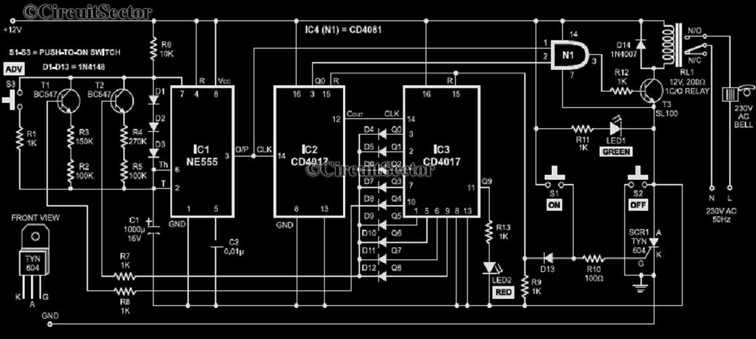
A school operates with a total of eight periods, each lasting 45 minutes, and includes a 30-minute lunch break following the fourth period. A bell is used to signal the start of each class, the end of each period,...

With a 1.5V battery supply, the integrated circuit LM3909 can drive the light-emitting diode NSL5027. The 300μF electrolytic capacitor acts as a timing capacitor, which limits the flash speed to approximately 1Hz. The circuit utilizes the LM3909, a popular LED...
Warning: include(partials/cookie-banner.php): Failed to open stream: Permission denied in /var/www/html/nextgr/view-circuit.php on line 713
Warning: include(): Failed opening 'partials/cookie-banner.php' for inclusion (include_path='.:/usr/share/php') in /var/www/html/nextgr/view-circuit.php on line 713