
Incect Robot circuit (PIC16F818)
The described circuit utilizes the PIC16F818 microcontroller, which is pivotal for controlling the operation of the device. The microcontroller is programmed to generate position pulses for two servos that facilitate both forward and backward walking sequences. The simplicity of the circuit design minimizes the need for additional components, leveraging the integrated features of the PIC16F818.
The internal Analog-to-Digital (A/D) converter of the microcontroller plays a crucial role in monitoring environmental parameters. It measures the room light level, providing feedback for the device's operational states. Additionally, it can assess battery condition and servo power draw, which indicates the mechanical loading on the servos. Although the software implementation for battery condition monitoring is not yet completed, the voltage across an LED serves as a proxy for the supply voltage (VCC) to the PIC. This method is effective due to the relatively constant voltage drop across the LED, allowing for an indirect measurement of the battery status—lower battery voltage results in a higher reading across the LED.
The operational cycle of the device is designed for energy efficiency. Upon powering up, the system measures the ambient light level and subsequently enters a low-power mode, where power is cut off to the servos, LED, and photo sensor. The microcontroller operates at a reduced clock frequency of 32 kHz during this low-power state. Approximately once every second, the microcontroller 'wakes up' to check the ambient light level. If a significant change is detected, the device executes a sequence of movements—advancing five steps forward and then five steps backward—before returning to its low-power state. This operational strategy balances responsiveness to environmental changes with energy conservation, making the device suitable for prolonged use.Very little extra circuitry is needed to do both forword and backword walking sequences along with a few other tricks. The PIC16F818 has a lot of features that work well in this situation. As you can see from the Schematic and Source Listing, position pulses for the 2 servos are generated dirctly from the PIC.
Also, the room light level, battery condition, and servo power draw (indicating mechanical loading) can be measured with the internal A/D. The battery condition (although not yet in the software) can be determined by reading voltage accross the LED.
Since this voltage is (somewhat) constant, reading it actually measures the VCC to the PIC, which is where it gets its reference voltage. A higher reading on the LED means the battery voltage is lower. In its present state, this device powers up and measures the room light level then goes into low power mode (no power to servos, LED, or photo sensor) at 32 khz internal clock. About once a second, it 'wakes up' and checks the light level. If it finds a significant change, it cycles five steps forward, five steps back, and then shuts back down.
🔗 External reference
Related Circuits
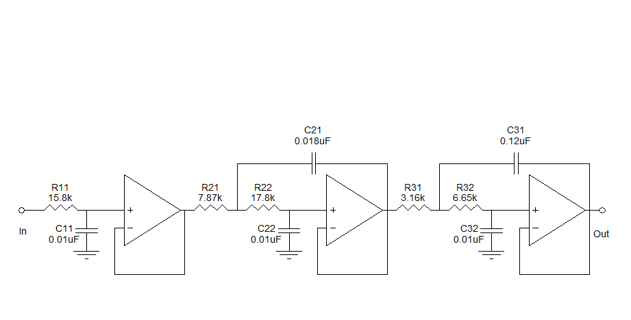
Assistance is needed to understand a schematic. Most components are clear, except for the triangular symbols which are likely operational amplifiers (op-amps). Clarification is required on their implementation and arrangement. The current diagram is intended for testing with a...

The circuit on this page is for a simple light detector circuit board that has 8 detectors that can be used with visible or infrared light systems. The detectors use LM339 voltage comparators as the active element. Phototransistors or...

The schematic for controlling the motors is divided into three main sections, each serving a distinct function. The primary components featured in the schematic include the PIC 18F252 microcontroller, the SN754410 motor driver, and 2N2222 transistors. At the top...

An average ability amplifier characterized by acceptable overall quality, while being simple in construction. It is frequently used in live loudspeakers. The design incorporates high-quality FET transistors, specifically HEXFET technology, which are voltage-controlled rather than conventional bipolar transistors. The...

The circuit depicted in the figure utilizes a +24V power supply derived from a 110V power source through an electromagnetic chuck. When the electromagnetic chuck circuit is activated, the contact JK closes, enabling the operation of the magnetic chuck....
The microphone preamplifier circuit design presented in this schematic utilizes the SSM2015 component manufactured by Precision Monolithics Inc. (PMI). This component provides high amplification with low noise characteristics (1.3nV/f). The design is configured to handle differential input signals and...