
Automatic School Bell Circuit PCB
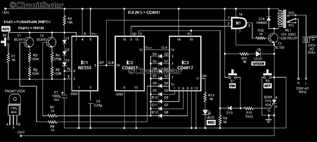
The electronic circuit described consists of a timing mechanism designed to manage the schedule of a school day. The 555 timer is set up in astable mode, which allows it to continuously oscillate and generate a square wave output. The frequency of this output can be adjusted by selecting appropriate resistors and capacitors in the circuit. In this application, the output pulse from the 555 timer is fed into a CD4017 decade counter, which counts the pulses and provides outputs at specific counts.
The CD4017 is a popular decade counter that has ten output pins, each corresponding to a count from 0 to 9. In this configuration, the output of the CD4017 is used to trigger the next stage of the circuit, which is the timing mechanism for the class periods and lunch breaks. The increase of the timing periods by a factor of ten ensures that the output from the 555 timer can be effectively utilized to manage longer intervals, specifically designed to match the school schedule of 45-minute class periods and a 30-minute lunch break.
The clock pulses are generated such that after the 555 timer completes its cycle, the CD4017 outputs will activate transistors T1 and T2. These transistors act as switches that control the power to the bell system. The diodes D4 to D12 are included in the circuit to prevent backflow of current and to ensure that the transistors are driven correctly by the outputs of IC3. This arrangement ensures that the bell rings at the appropriate times, signaling the start and end of each class period and the lunch break, thereby maintaining the school's schedule efficiently.
Overall, this circuit provides a reliable and automated method to manage the timing of a school day, improving the efficiency of transitions between periods and ensuring that students and staff are informed of schedule changes through an audible signal.Consider that a school has a total of eight periods with a lunch break after the fourth period. Each period is 45 minutes long, while the duration of the lunch break is 30 minutes. The bell will be ringed to start the class, end of each period, extension at lunch break etc. To ring the bell to start first period, the peon needs to momentarily pres s switch S1. The 555 timer IC is configured as an astable multivibrator whose clock output pulses are fed to the CD 4017 IC. IC2 increases the time periods of IC1 (4. 5 and 3 minutes) by ten times to provide a clock pulse to IC3 every 45 minutes or after 30 minutes, respectively.
When the class periods are going on, the outputs of IC3 switch on transistors T1 and T2 via diodes D4 through D12. 🔗 External reference
Related Circuits

The circuit activates a light corresponding to the first button pressed in a "Who's First" game. Three stages are illustrated, but the circuit can be expanded to accommodate any number of buttons and lamps. The described circuit operates as a...
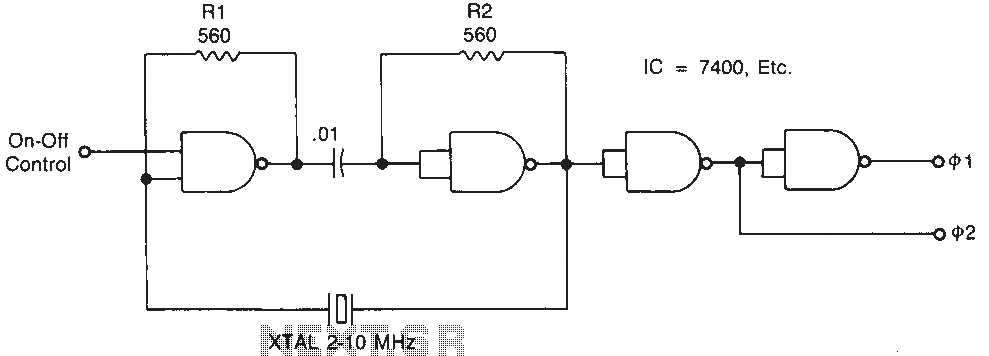
Temperature-stable resistors R1 and R2 are used in NAND gate configurations, ensuring that the switches operate in the linear region. Capacitor C1 functions as a DC component at the operating frequencies. Additionally, the impedance must remain below 0.1 ohm....
Building circuits to interface an Amiga A1200 to a PC AT/ATX power supply and tower case. To create a reliable interface between an Amiga A1200 and a PC AT/ATX power supply and tower case, it is essential to design a...

An NE555 timer integrated circuit (IC) configured in a specific manner can identify the absence of a pulse or an unusually long duration between two successive pulses in a pulse train. Such circuits are applicable for detecting the intermittent...
The circuit consists of a light metering circuit and a flash circuit, as illustrated in the accompanying image. It is designed for use with integrated cameras such as POPTICS, Franka X-500, and WIZEN-860S. The circuit includes the following components:...
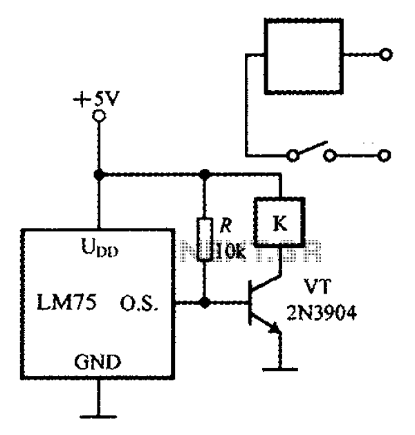
The circuit features simple smart temperature sensors utilizing an I2C bus interface, designed as a thermostat controller circuit. It employs the LM75 temperature sensor connected to a 2N3904 transistor, which drives a relay coil. The relay operates based on...
Warning: include(partials/cookie-banner.php): Failed to open stream: Permission denied in /var/www/html/nextgr/view-circuit.php on line 713
Warning: include(): Failed opening 'partials/cookie-banner.php' for inclusion (include_path='.:/usr/share/php') in /var/www/html/nextgr/view-circuit.php on line 713