
Alternator Regulator Circuit
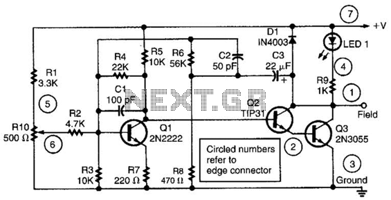
The alternator regulator circuit operates by employing a 3-transistor DC amplifier configuration, which effectively manages the voltage supplied to the alternator's field winding. In this design, one terminal of the field winding is connected to the +12V supply, while the other terminal is grounded, creating a pulled-up field system. This configuration allows for efficient control of the magnetic field generated by the alternator, which in turn regulates the output voltage and current to charge the battery and power the vehicle's electrical systems.
The circuit's ability to monitor the battery state is crucial for maintaining optimal performance. It incorporates a resistive voltage divider that samples the battery voltage. The output from this divider provides feedback to the transistor amplifier, enabling it to adjust the field voltage dynamically. When the battery voltage drops below a predefined threshold, the regulator increases the voltage at the field terminal, enhancing the magnetic field strength and boosting the alternator output. Conversely, if the battery voltage exceeds the desired level, the regulator reduces the field voltage, preventing overcharging and potential damage to the battery.
Overall, this alternator regulator design ensures efficient charging, prolongs battery life, and maintains the reliability of the vehicle's electrical system by continuously adapting to changing conditions. This alternator regulator uses a 3-transistor dc amplifier, and is designed for a pulled up field system, where one side of the alternate field returns to the +12-Vsupply, and the other end is pulled toward ground. The circuit monitors the state of the battery through a resistive divider and causes the voltage to change at the field terminal. 🔗 External reference
Related Circuits
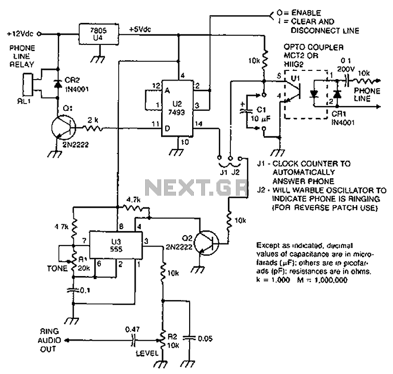
Check the loop circuit for an automatic telephone answering system or a tone generator for use in reverse automatic repair. The loop circuit in an automatic telephone answering system is designed to detect incoming calls and activate the answering mechanism....
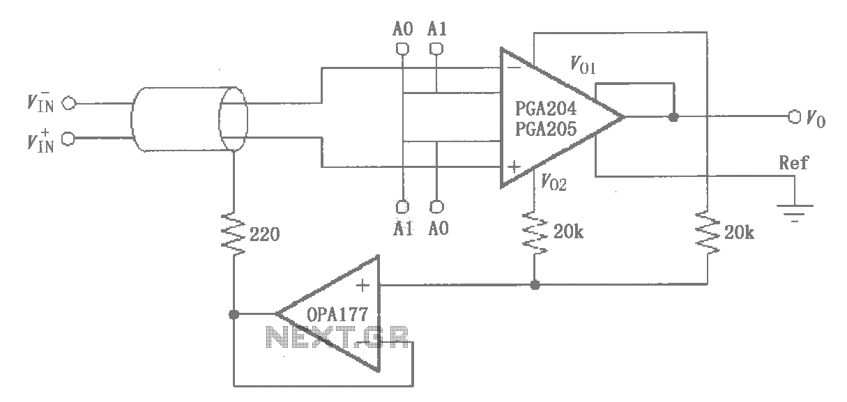
The circuit illustrated by the PGA204/205 pertains to the shield drive circuit shown in the figure. It is demonstrated through interference theory and practical application that the cable shield, when transmitting weak signals, maintains a certain potential. This configuration...
A voice sound recording circuit is desired, which, when triggered, will play the recorded sound through an amplifier circuit. The proposed voice sound recording circuit can be designed using a microcontroller or dedicated audio recording ICs, along with an amplifier...
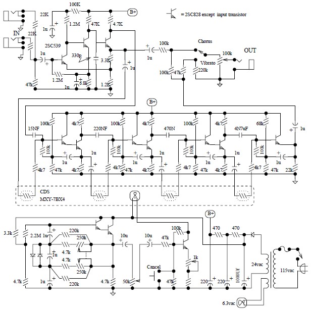
The Univibe is a footpedal-operated phaser or phase shifter designed to generate chorus and vibrato simulations for electric organs or guitars. It was introduced in the 1960s by Shin-ei, with the intention of emulating the "Doppler sound" characteristic of...
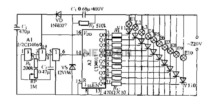
The digital integrated circuit consists of a controller for a string of ten road flashing lights, which drives the El-El0 string lights in a flashing cycle. The system utilizes a ten-count decoder, specifically the CD4017 digital integrated circuit. When...
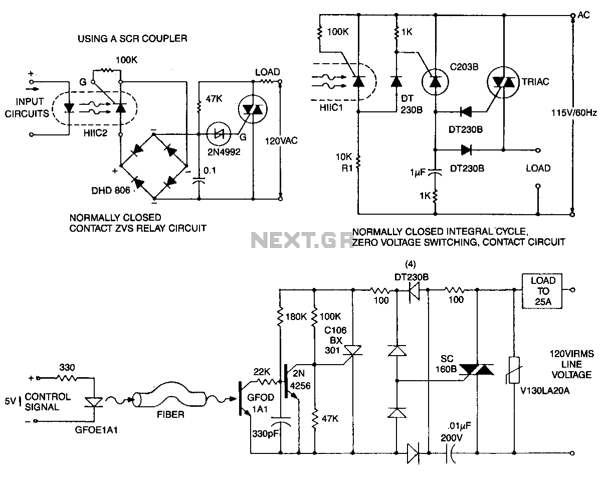
This circuit is effective for lamp and heater loads. Some circuits driving reactive loads require integral cycling and zero-voltage switching when an identical number of positive and negative half-cycles of voltage are applied to the load during a power...
Warning: include(partials/cookie-banner.php): Failed to open stream: Permission denied in /var/www/html/nextgr/view-circuit.php on line 713
Warning: include(): Failed opening 'partials/cookie-banner.php' for inclusion (include_path='.:/usr/share/php') in /var/www/html/nextgr/view-circuit.php on line 713