
Automatic telephone answering and ringtones indicator circuit diagrams
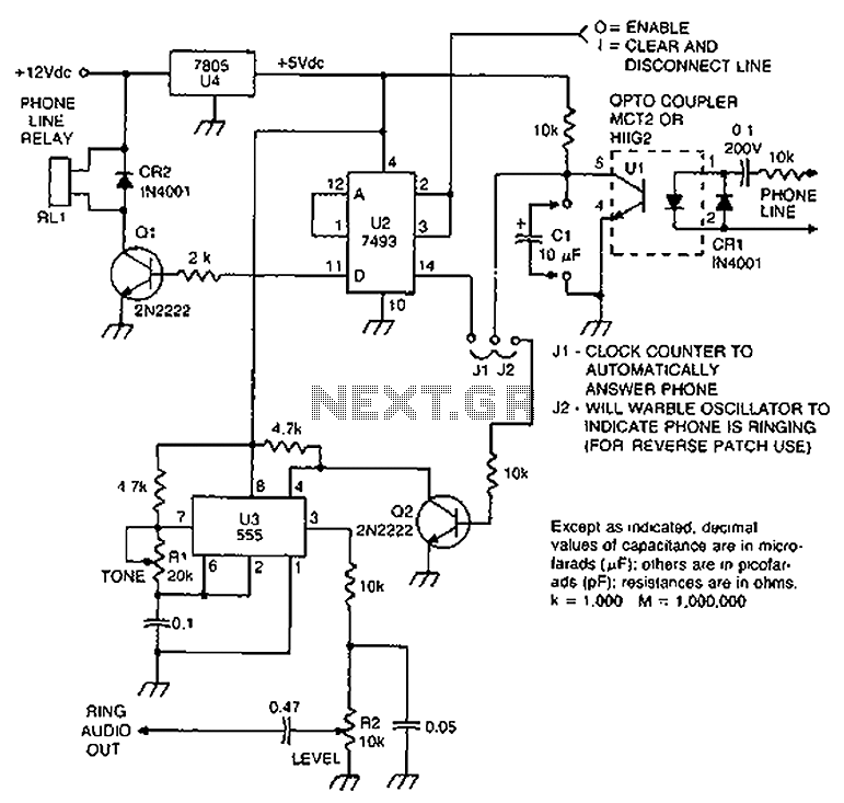
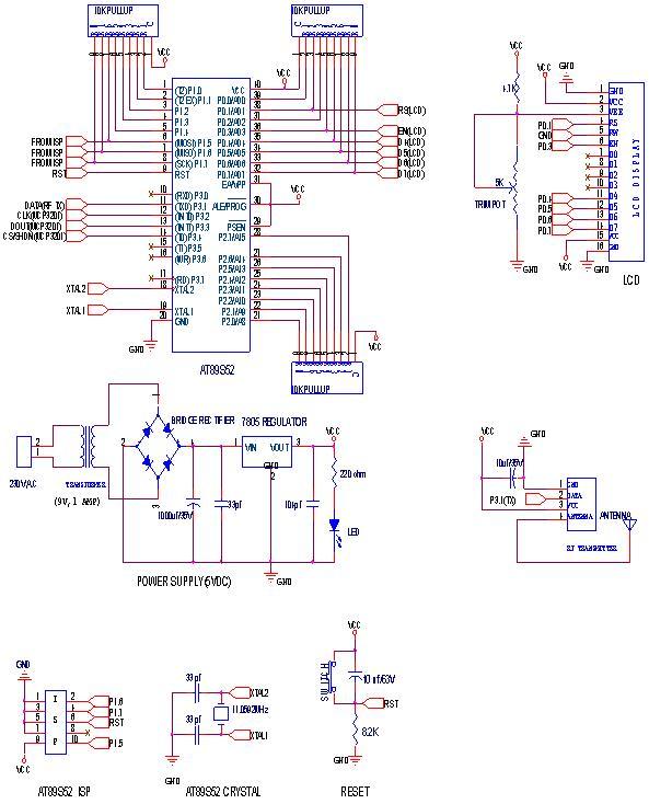
The loop circuit in an automatic telephone answering system is designed to detect incoming calls and activate the answering mechanism. This circuit typically consists of a series of components that work together to monitor the telephone line's status. When a call is received, the circuit detects the loop current, which is the flow of electric current through the telephone line.
Key components of the loop circuit may include a relay, which is used to switch the answering machine on or off, and a microcontroller that processes the signals received from the telephone line. The microcontroller can be programmed to recognize specific tones or signals, such as the ringing signal from an incoming call, and respond accordingly by activating the answering function.
In the context of a tone generator used for reverse automatic repair, the circuit may also incorporate a tone generator IC (integrated circuit) that produces specific audio frequencies. This is useful for testing and troubleshooting telephone lines, as it allows technicians to generate a test tone that can be sent through the line to verify its functionality. The tone generator can be activated by the same loop circuit, providing versatility in its application.
Overall, the design of the loop circuit must ensure reliable detection of incoming calls and proper operation of the answering system or tone generator, with careful consideration of component selection and circuit layout to minimize noise and interference. Check loop circuit for automatic telephone answering or tone generator for use reverse automatic repair.
Related Circuits
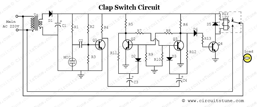
This is a simple electronic circuit for a clap switch project. It is suitable for beginner electronics learners who enjoy experimenting with new projects. The circuit can turn on or off a 220V electronic device, such as a fan...
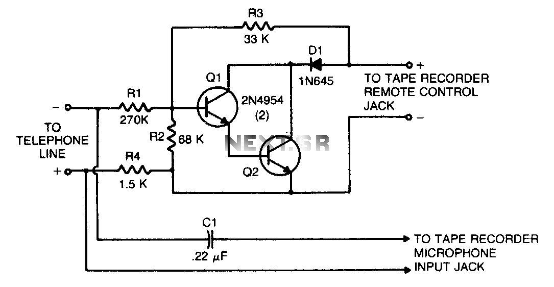
This circuit transforms a tape recorder into a fully automatic device for recording telephone conversations without requiring an external power source. The voltage at the switch terminals of the tape recorder is applied to a pair of Darlington-connected transistors,...
This house FM transmitter for your stereo or any other amplifier provides a strong signal strength up to a distance of 500 meters with a power output of about. This FM transmitter is designed to enhance audio transmission capabilities for...
This is a very simple crystal receiver circuit for short wave band and can be used with headphones. The described circuit is a basic crystal receiver designed to operate within the shortwave frequency band. The primary components of this circuit...
RF Wireless Data Transfer communication circuit diagram. A wireless communication interface was implemented to facilitate data transfer from one point to another using RF technology. The RF Wireless Data Transfer communication circuit utilizes radio frequency (RF) technology to establish a...
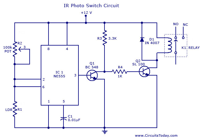
A simple photo switch circuit using the NE555 IC with a diagram and schematic. This photo switch activates a relay when light intensity exceeds a certain threshold. It serves as a light sensor circuit suitable for both home and...