
univibe pedal circuit diagram

The Univibe circuit operates by modulating the phase of the input signal to create a rich, swirling effect that is reminiscent of a Leslie speaker. The modulation is typically achieved using a combination of light-dependent resistors (LDRs) and a light source, often a bulb. The LDRs change their resistance based on the intensity of the light, which is modulated by the bulb, creating the desired phasing effect. The circuit may include a depth control to adjust the intensity of the modulation and a speed control to vary the rate of the effect, allowing for versatile sound shaping.
The octave fuzz circuit is designed to produce a distinct octave effect alongside a fuzz tone. The key components include transistors configured to create a rectified signal, which contributes to the chewy texture of the fuzz. The optional mode allows users to select between the full octave fuzz and a standard fuzz effect, making it adaptable for different musical styles.
The DOD FX75 Flanger circuit employs a Bucket Brigade Device (BBD) to achieve a time delay effect, which is modulated to create a flanging sound. The use of a low-noise BBD ensures that the signal remains clean while the delay is manipulated. The TL022C op-amp is used to amplify the signal, while the CD4007 provides the necessary analog switching capabilities.
The Tube Distortion Pedal circuit utilizes a dual op-amp configuration to amplify the guitar signal before it is distorted. The LM340K-12V Voltage Regulator ensures stable operation of the circuit by providing a consistent voltage supply, critical for maintaining sound quality.
The Univox Super-Fuzz Pedal circuit employs a unique design that allows for octave generation through a differential amplifier configuration. This design provides a distinctive sound that has contributed to its popularity among guitarists seeking a unique tonal character.
The Maestro Boomerang/Wah-Wah Pedal circuit is designed to provide a wah effect, which is achieved by varying the frequency response of the signal. The use of specific transistors enables the pedal to produce a wide range of tonal variations, making it a versatile tool for guitarists looking to enhance their sound. Detailed construction instructions provide guidance for builders to replicate this classic effect.The Univibe is actually a footpedal-operated phaser or phase shifter for generating chorus and vibrato simulations for electric organ or guitar. It was introduced in the 1960s by Shin-ei, and was intended to emulate the "Doppler sound" of a Leslie speaker.
Although not a really successful Leslie-simulator, the Univibe has turn out to be an. Here the circuit diagram of octave fuzz guitar effect pedal. This guitar effect unit is great sounding octave fuzz, with an optional mode of just fuzz. The fuzz is really a absolutely rectified signal and is fairly chewy. For some the Fuzz alone could possibly not be loud enough, this could be fixed by raising. This is the circuit diagram of DOD FX75 Flanger guitar effect pedal. The circuit drawn by Fabian P. Hartery Components CD4007 dual complementary pair with inverter; (RCA) TL022C low power dual operating amplifier; (texas instruments) MN3007 audio signal delay, 1024 stage low noise BBD (5. 12-51. 2 msec delay) MN3101 clock generator for Bucket Brigade Device/BBD. The following circuit is Tube Distortion Pedal for guitar effect. The circuit designed by Ron Black. Notes: IC1 : 747 dual op-amp, other ICs may be substitued but pinout will different. You should check the datasheet IC2 : LM340K-12V Voltage Regulator All resistors are 1/2 W Bridge Rectifier - Full wave bridge recitifier, 50 Volts, .
This is the circuit diagram of Univox Super-Fuzz Pedal. This pedal is actually a 69-to-early 70`s design that consists of two special capabilities. They are the octave generation effect from the differential-pair-with-collectors -tied-together along with the option of just a clipping amplifier or a 1kHz notch for different sounds. The odd-diffamp is basically a full. Here the circuit diagram of Maestro Boomerang / Wah-Wah Pedal for electric guitar effect. Note: Transistors Q1 and Q2 were designated P-2356 Download schematic in pdf document HERE Step by step about how to build Maestro Boomerang Wah Pedal guitar effect, visit this page
🔗 External reference
Related Circuits
This amplifier is designed for outdoor installation and is connected to an indoor power line box. It utilizes either 50-ohm or 75-ohm coaxial cables for the connection between indoor and outdoor units. The amplifier circuit board is depicted in...
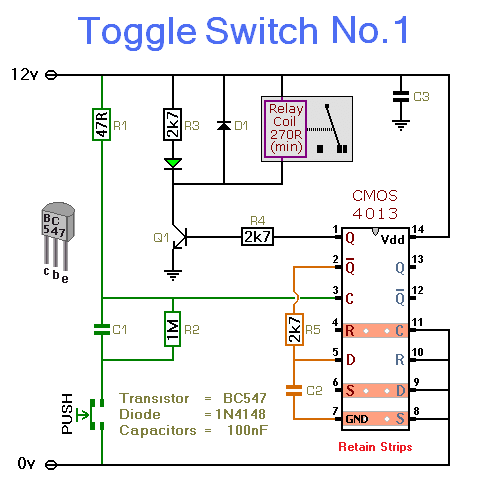
This simple circuit will energize and de-energize a relay with the push of a button. Pressing the button once will energize the relay, while pressing it a second time will de-energize the relay. The accompanying circuit provides a solid...
A wide range auto turn OFF timer covering 1 minute to 20 hours in three ranges with S1. As soon as power is applied to the circuit, the IC1 [555] starts to oscillate and feeds clock pulses to the...
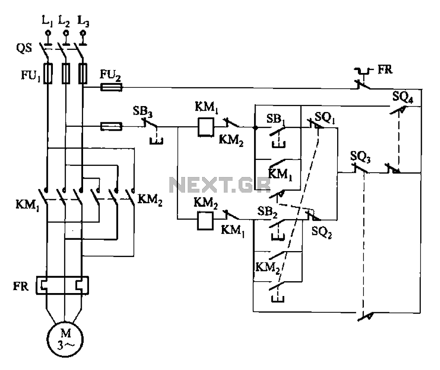
The circuit illustrated in Figure 3-132 represents an automatic round-trip plug braking circuit. To prevent or limit malfunctions of switch SQ1 and switch SQ2 that could lead to accidents, two additional protection limit switches, S03 and S04, have been...
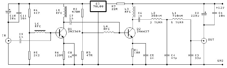
A high-efficiency, simple two-transistor VHF amplifier electronic circuit project can be developed using the provided circuit diagram. This VHF amplifier circuit achieves a significant efficiency with a gain of approximately 16 dB and does not require any tuning or...
This circuit generates dual-tone bell ringing similar to most doorbell units. It can be used in various applications beyond just doorbells. Several options will be provided in the notes to accommodate different needs. The circuit, as depicted in the...