
AM base circuit
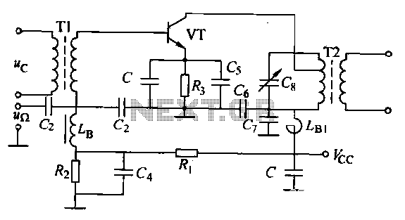
The circuit operates within the framework of amplitude modulation, where the information signal modifies the amplitude of a high-frequency carrier wave. The high-frequency bypass capacitor (C) is crucial for stabilizing the circuit by preventing high-frequency noise from affecting the performance of the AM signal. It allows AC signals to pass while blocking DC, ensuring that the modulation process remains unaffected by fluctuations in the power supply.
Transformers T1 and T2 are integral to the circuit, facilitating the transfer of energy between different stages while maintaining the integrity of the high-frequency signals. These transformers are designed to efficiently couple the signal at the desired carrier frequency, ensuring minimal loss and optimal performance.
The LC resonant circuit is tuned to the carrier frequency, enabling selective amplification of the desired signal while filtering out unwanted frequencies. The passband of 2Fr indicates the range of frequencies around the carrier frequency that the circuit can effectively process, allowing for the transmission of modulated signals with minimal distortion.
For the detection of the modulated signal, a low-pass filter is employed to isolate the baseband signal from the high-frequency components. The square-diode detector operates by rectifying the incoming modulated signal, allowing for the recovery of the original information signal. The term "small signal square-detector" highlights the circuit's capability to handle low-amplitude signals, which is essential in applications where the input signal is weak, such as in communication systems and radio receivers. This design emphasizes the importance of precision in signal processing, ensuring reliable detection and reproduction of the transmitted information.AM base for small-signal amplitude modulation, the circuit as shown C is a high frequency bypass capacitor. Tl, T2 is a high frequency transformer, LC resonant circuit at the carrier frequency , passband is 2Fr. . Change, and then implement the detector through a low-pass filter, this detection method called square-diode detector.
Due to the small high-frequency input signal amplitude, fork called small signal square-detector.
Related Circuits
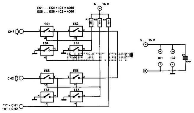
This combination sync stripper and universal video interface can solve various problems, including interfacing Super Nintendo with other devices, video overlay, and locking TV frames for scopes. Kits, fully tested units, and custom cable assemblies are available through Redmond...
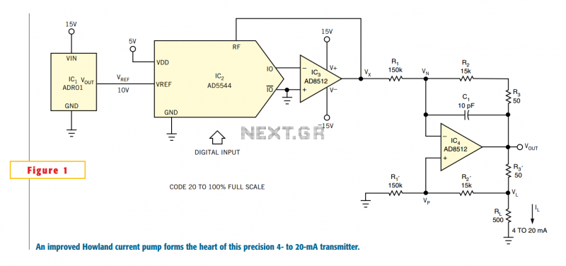
One of the key challenges in the design of 4- to 20-mA current transmitters is the voltage-to-current conversion stage. Conventional transmitters use multiple op amps and transistors to perform the conversion function. These approaches have been around for a...
Using this low cost project, one can reproduce audio from a TV without disturbing anyone. It does not use any wire between the TV and headphones. Instead of a pair of wires, it uses invisible infrared light to transmit...
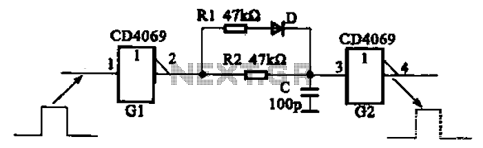
The inverter circuit using CD4069 is configured with a delay and width adjustment. When the output of the inverter (G1) is high, the capacitor (C) charges through resistor (R1) and diode (D). The voltage across capacitor C quickly reaches...
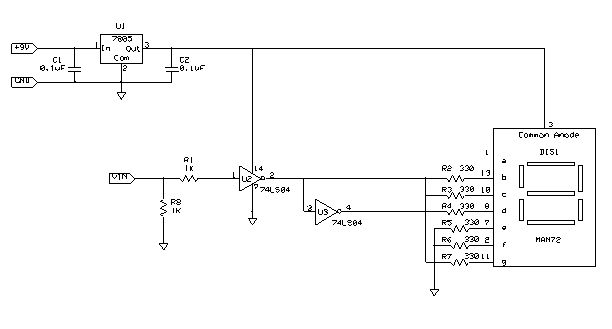
The following instructions outline the process for constructing a practical test tool designed for troubleshooting and analyzing digital and microcontroller circuits. The complete assembly and instruction manual can be downloaded from the provided web link: Don's Projects. To begin,...
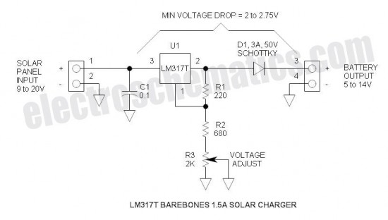
This is the simplest and most affordable solar battery charger that a hobbyist can create. It has some drawbacks compared to other similar controls, but offers unique advantages. The solar battery charger circuit is designed to harness solar energy to...
Warning: include(partials/cookie-banner.php): Failed to open stream: Permission denied in /var/www/html/nextgr/view-circuit.php on line 713
Warning: include(): Failed opening 'partials/cookie-banner.php' for inclusion (include_path='.:/usr/share/php') in /var/www/html/nextgr/view-circuit.php on line 713