
Infrared Headphone Amplifier circuit
The described project is an infrared audio transmission system that enables wireless audio reproduction from a television to a pair of headphones. The system consists of two main components: the IR transmitter and the IR receiver.
The IR transmitter is designed to capture audio signals from the TV using an audio output transformer. This transformer is connected in reverse, allowing it to couple the audio output from the TV to the transmitter circuit. The audio signal is then amplified using a two-stage transistor amplifier, which utilizes transistors BC547 and BD140. These transistors are responsible for increasing the audio signal strength before it drives two infrared LEDs that are connected in series. The transmitter can be powered by either a 9V mains adaptor or a 9V battery, providing flexibility in power source selection. An LED indicator is integrated into the transmitter circuit to signify when the system is powered on.
The IR receiver is equipped with a three-stage transistor amplifier, with the first two transistors (BC549C) dedicated to amplifying the audio signal received from the IR LEDs. The third transistor (BD139) serves the purpose of driving the headphones. An adjustable potentiometer is included in the receiver circuit to allow users to fine-tune the audio output for optimal clarity. To ensure maximum transmission range, the photo transistor within the receiver should be oriented towards the IR LEDs of the transmitter. The system is capable of operating at a distance of up to 6 meters without any lenses, although the range can be extended with the use of lenses and reflectors. Additionally, the receiver can also be powered by a 9V battery, making the entire system suitable for portable applications.
This infrared audio transmission system provides a practical solution for listening to television audio without disturbing others, making it ideal for use in shared living spaces or during late-night viewing.Using this low cost Project one can reproduce AUDIO from TV without disturbing anyone. It does not use any wire between TV and HEADPHONE. In place of pair of wires it uses invisible Infrared light to transmit audio signals from TV to Headphone. Without using any lens a range of up to 6 meters is possible. Range can be extended by using Lenses and Reflectors with IR sensors comprising transmitters and receivers.
IR transmitter uses two-stage transistor amplifier to drive two IR leds connected in series. An audio output transformer is used (in reverse) to couple Audio output from TV to the IR transmitter. Transistors (BC547) & (BD140) amplify the audio signals received from TV through audio transformer low impedance output windings (lower gauge or thicker wire) are used for connection to TV side while high impedance are connected to the IR transmitter. This IR transmitter can be powered by 9v mains Adaptor or 9v Battery. Led in transmitter circuit functions as power-on indicator. IR receiver uses 3-stage transistors amplifier. The first two transistors (BC549c)from audio signal amplifier. While the third transistor(BD139)is used to drive a headphone. Adjust potmetre for max clarity. Direct photo transistor towards the IR Leds of transmitter for max range. A 9v Battery can be used to receiver circuit for portable operation 🔗 External reference
Related Circuits
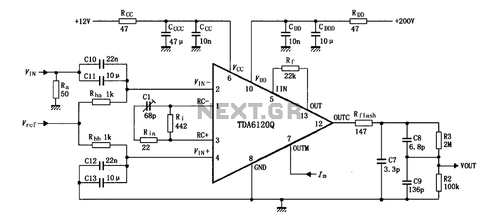
Feedback has indicated that the TDA6120Q test circuit, as shown in the figure, utilizes an input signal (Vi) composed of resistors Ra and capacitors C10 and C11, which are fed into the TDA6120Q at pins 2, 3, and 4....
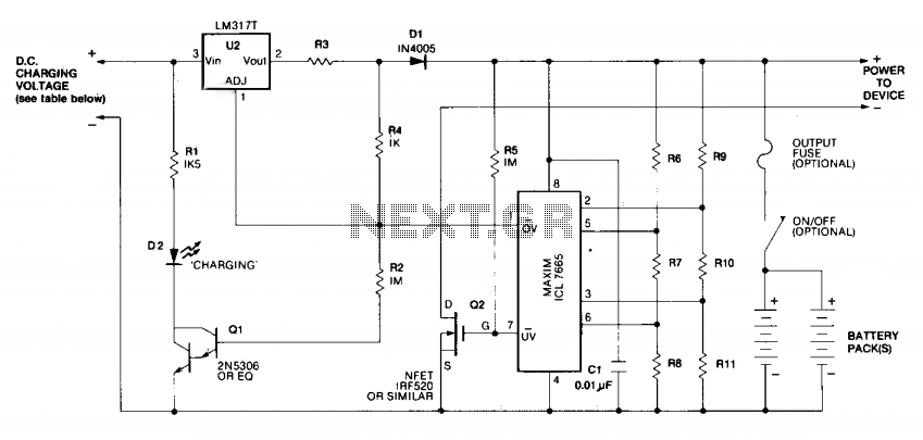
Charging is achieved using a constant current of 60 mA for AA cells, reaching a cutoff voltage of 2.4 V per cell, at which point the charging process must be terminated. The charging system is designed for multi-cell battery...
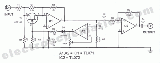
The function of this automatic volume control circuit is to amplify signals without distorting their dynamic compression. The amplitude differences in the signal are leveled off, eliminating disturbing effects. This technique avoids overcompensation in volume. The circuit is utilized...
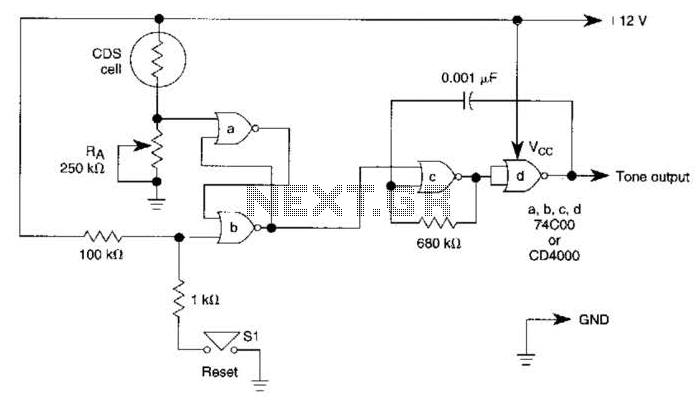
A decrease in the resistance of the CDS cell when light strikes it activates latch A and B, enabling tone oscillator C and D, which produces an output of about 1000 Hz. RA sets the trip level. SI resets...
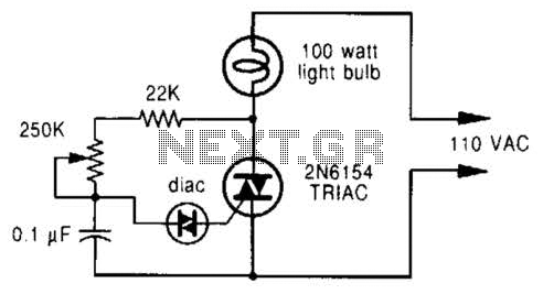
A phase-controlled dimmer delays the triac turn-on to a selected point in each successive AC half cycle. This circuit is suitable only for incandescent lamps, heaters, soldering irons, or universal motors that have brushes. A phase-controlled dimmer is an electronic...
Today, it is no longer necessary to use discrete components for constructing oscillators. Many manufacturers now offer ready-made voltage-controlled oscillator (VCO) integrated circuits (ICs) that require only a few external components to determine the frequency. An example of such...
Warning: include(partials/cookie-banner.php): Failed to open stream: Permission denied in /var/www/html/nextgr/view-circuit.php on line 713
Warning: include(): Failed opening 'partials/cookie-banner.php' for inclusion (include_path='.:/usr/share/php') in /var/www/html/nextgr/view-circuit.php on line 713