
Logic Probe Circuit Schematic Diagram
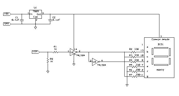
The described test tool is a logic probe, which serves as a fundamental device in digital electronics for testing and diagnosing circuit functionality. The logic probe operates by indicating the logic level present at a given point in a circuit, typically represented by LED illumination. When the device is powered by a 9V battery, the LED will display a specific character, such as "L," to signify that the probe is operational and ready to test.
The assembly process involves several critical steps. First, the 9V battery must be securely connected to the battery clip, ensuring proper polarity to avoid damage to the circuit. The 7-segment LED display is integrated into the design, providing a clear visual indication of the probe's status. The soldering of wires is essential for establishing connections between the probe and the PCB. The red wire is connected to the designated "Probe" location on the PCB, which is the point where the logic level will be measured. The black wire serves as a ground connection, providing a reference point for the measurements taken by the probe.
Upon completion of the assembly, the logic probe can be utilized to analyze digital signals in various circuits, including microcontroller applications. By probing different points in a circuit, the user can determine the presence of high (logic 1) or low (logic 0) signals, facilitating the identification of faults or verifying circuit operation. This tool is invaluable for engineers and technicians working with digital electronics, as it allows for efficient troubleshooting and ensures proper functionality of the circuits under test.The following instructions will allow you to build a practical test tool for troubleshooting and analyzing digital and microcontroller circuits. The complete Assembly and Instruction Manual can be downloaded from the the following web link: Don`s Projects Snap a 9V Battery to the battery clip.
The Letter L should be displayed on the 7 Segment LED Display. Next soldered a red wire on the pcb where "Probe" is located. Last, soldered a black wire next to the black wire attached to the 9V Battery Clip. Now, the Logic Probe is ready to trouble or analyze digital or microcontroller circuits. 🔗 External reference
Related Circuits
The piezo diaphragm can originate from a music card, and if two or three diaphragms are available, they can be connected in parallel, as illustrated in the diagram, to observe their impact on the output frequency. The only component...
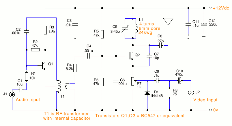
This is a small TV transmitter circuit that transmits in VHF, utilizing negative sound modulation and PAL video modulation. It is suitable for countries that use the B and G system. T1 refers to a type of transformer. The...

The CD4013 is a dual D flip-flop that operates on the rising edge of the clock signal. Its internal block diagram and pin configuration are provided. This device is part of the standard model C043 and the GB model...

The schematic diagram below illustrates a high voltage generator circuit. This circuit employs a 4049 hex inverter configured as an oscillator, and it can utilize an ignition transformer from an automotive engine. A fly-back transformer may also be suitable....
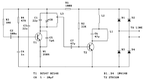
This FM spy telephone circuit is connected in series with the phone line. When there is a signal on the wires, this transmitter will radiate airwaves through the wires. This FM spy telephone circuit operates by integrating with the existing...
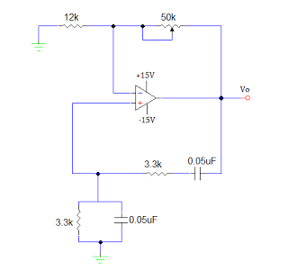
An operational amplifier-based sine wave generator circuit, commonly known as a Wien bridge oscillator, is recognized for its simplicity and stability. The Wien bridge oscillator connects the Wien bridge circuit between the amplifier's input and output terminals. The bridge...