
AM/cw 12-meter band transmitter

Continuous Wave (CW) modulation is a fundamental technique in radio communications, characterized by its simplicity and effectiveness. In a CW transmitter, the modulation is achieved by turning the radio frequency (RF) signal on and off, which corresponds to the transmission of Morse code. The transmitter generates a constant amplitude RF signal, which is interrupted to create distinct dots and dashes, representing different characters.
The design of a basic CW transmitter involves several key components. The heart of the transmitter is typically an oscillator circuit that generates the RF signal. This oscillator can be a crystal oscillator or a more complex phase-locked loop (PLL) circuit, depending on the desired frequency stability and accuracy. The output of the oscillator is fed into an amplifier stage to boost the signal strength, ensuring it can be transmitted over long distances.
To modulate the RF signal, a keying circuit is employed. The keying circuit can be as simple as a mechanical switch or a more sophisticated electronic switch, such as a transistor or a relay. When the key is pressed, the circuit completes, allowing the RF signal to pass through, and when released, the circuit opens, stopping the transmission. This on-off keying creates the CW signal, which can be transmitted through an antenna.
The antenna used in CW transmission is typically a simple dipole or a vertical antenna, designed to efficiently radiate the RF energy into the surrounding environment. The choice of antenna depends on the operating frequency and the desired radiation pattern.
One of the challenges with CW transmission is that the signal is difficult to detect amidst background noise, particularly on conventional receivers. The faint modulation of the background noise can make it hard for operators to discern the CW signals, necessitating the use of specialized CW receivers or filters to improve signal clarity.
CW remains a popular mode of communication in amateur radio and emergency communication due to its simplicity, low power requirements, and effectiveness over long distances. The ability to transmit information using minimal bandwidth makes CW an efficient choice for various applications, even in the modern era of digital communications.CW is the simplest form of modulation. The output of the transmitter is switched on and off, typically to form the characters of the Morse code. CW transmitters are simple and inexpensive, and the transmitted CW signal doesn`t occupy much frequency space (usually less than 500 Hz).
However, the CW signals will be difficult to hear on a normal receiver; you`ll just hear the faint quieting of the background noise as the CW signals are transmitted. This was the first type of modulation used for communicating signals from one point to another and is still the simplest to understand. A radio frequency current has a constant amplitude in absence of modulation and this constant amplitude RF carries no
🔗 External reference
Related Circuits
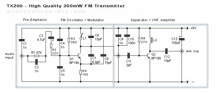
The TX200 is an advanced and significantly larger VFO/VCO FM transmitter, recognized as one of the best transmitters available. It is a 200mW FM transmitter designed for stereo PLL applications, providing a wide range for broadcasting music throughout a...
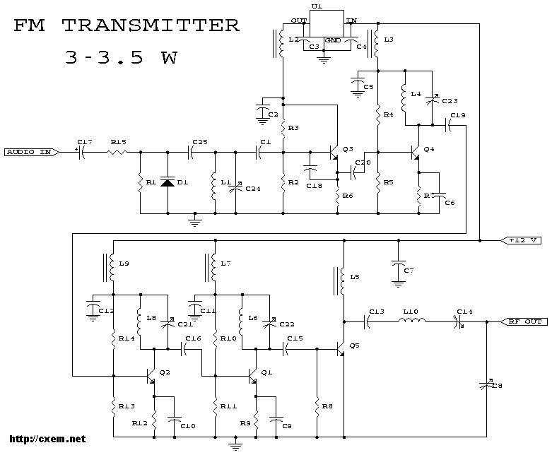
3-3.5 Watt FM Transmitter. This is the schematic for an FM transmitter with 3 to 3.5 W output power that can be used between 90 and 110 MHz. Although the stability is not so bad, a. The 3-3.5 Watt FM...

The equalizer discussed in this article is appropriate for use with high-fidelity installations, public address systems, mixers, and electronic musical instruments. The equalizer is an essential audio processing device that allows for the adjustment of specific frequency bands within an...
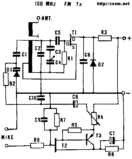
Small Radio Transmitter. This article contains information about building a small radio transmitter, which has a PCB measuring 1.75 x 2.5 inches (45 mm x 68 mm) and offers a range of approximately 30 yards. The small radio transmitter is...
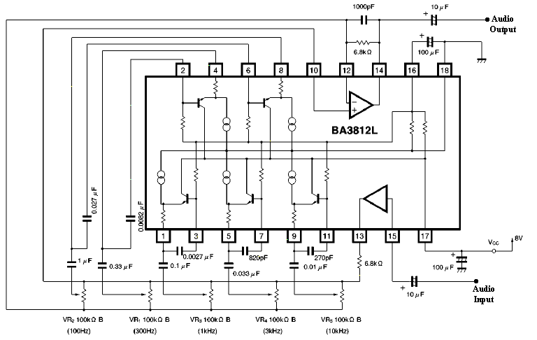
This section discusses a series of 5-band equalizer circuits utilizing a single integrated circuit (IC) BA3812L, which is designed for high-fidelity (hi-fi) audio applications. The BA3812 IC features a 5-point equalizer with all functions integrated within the chip. The...
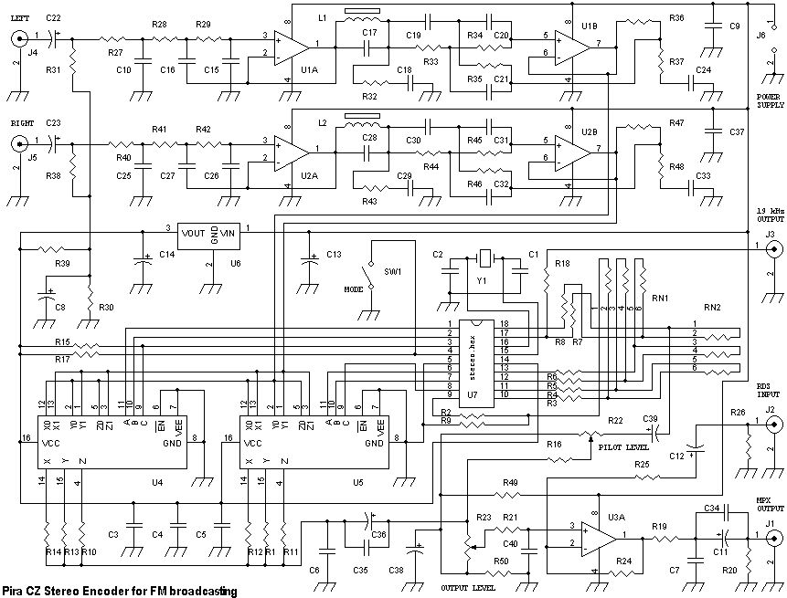
This stereo encoder is a halfway between analogue and digital processing. It combines the best from both domains to provide high-quality and easy to build device. The sampling frequency used in this stereo encoder is 97 times higher than...