
Small Radio Transmitter
The small radio transmitter is designed for basic communication applications and is suitable for hobbyists and educational purposes. The printed circuit board (PCB) dimensions of 1.75 x 2.5 inches (45 mm x 68 mm) allow for compact integration into various projects. The transmitter operates in the FM or AM band, depending on the design specifications, and is capable of broadcasting audio signals wirelessly within a range of approximately 30 yards.
Key components of the transmitter may include an oscillator circuit, which generates the carrier frequency, a modulator circuit to encode the audio signal onto the carrier wave, and an antenna for radiating the signal. The oscillator can be implemented using a simple transistor or an integrated circuit (IC) designed for RF applications. The modulator circuit typically employs a combination of resistors, capacitors, and transistors to ensure proper signal modulation.
Power supply considerations are crucial for the operation of the transmitter. A regulated DC power source, such as batteries or a wall adapter, should be used to ensure stable operation. Additionally, filtering capacitors may be included in the design to reduce noise and improve signal quality.
The antenna design plays a significant role in the effective transmission of signals. A simple wire antenna can be used, with its length adjusted to the frequency of operation to optimize performance. Proper placement of the transmitter and antenna can further enhance the effective range and clarity of the transmitted signal.
Safety precautions should be taken into account, particularly in regard to transmission power levels and frequency regulations to avoid interference with licensed radio communications. Overall, this small radio transmitter project offers a practical introduction to RF design and wireless communication principles.Small Radio Transmitter. This article contains information about building a small radio transmitter, which has a PCB 1.75 x 2.5 (45mm x 68 mm) and has a range of about 30 yards or. 🔗 External reference
Related Circuits

The Poppet is a half-watt AM transmitter designed by Mr. Doug Gibson of England. The original design was published in issue 84 of SPRAT, the newsletter of the GQRP Club. The version presented here incorporates modifications suggested by Steve...
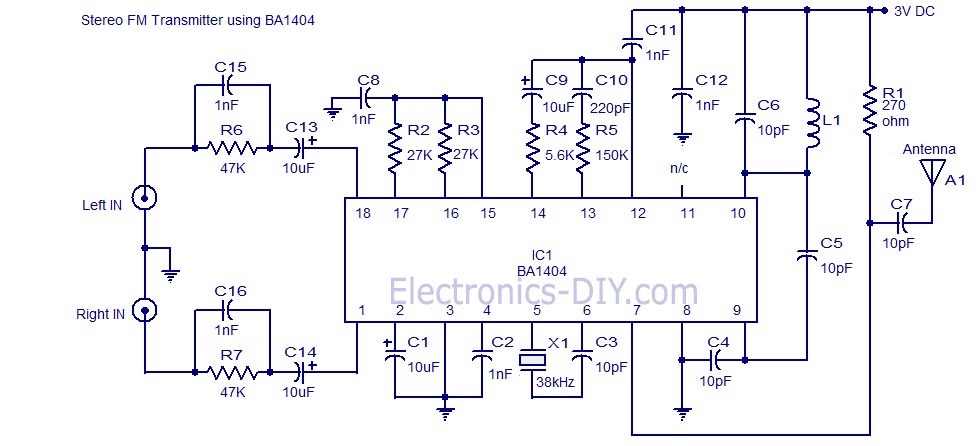
A high-quality stereo FM transmitter circuit is presented. This circuit utilizes the BA1404 integrated circuit from ROHM Semiconductors. The BA1404 is a monolithic FM stereo modulator that includes a built-in stereo modulator, FM modulator, and RF amplifier. The FM...
The circuit is presented, consisting of a language and sound circuit FM transmitter. It is simple and easy to manufacture, compatible with ordinary FM radios, allowing for potential listening scenarios and preventive measures. The FM transmitter circuit is designed to...
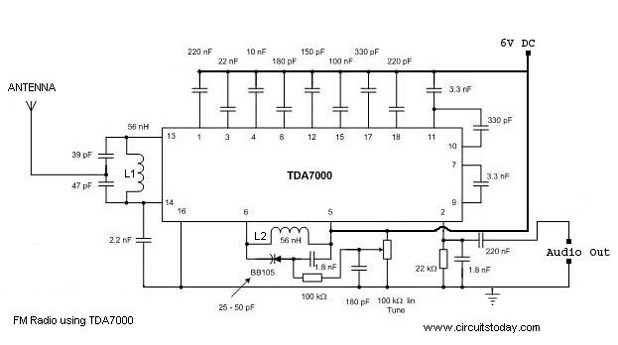
A simple FM radio circuit with a diagram and schematic using the IC TDA 7000. This low-cost single-chip FM radio circuit design is easy to assemble and is suitable for creating a portable FM radio. The FM radio circuit utilizing...
The schematic presented is a circuit for a 555 tracking transmitter. The 555 timer is a well-known versatile integrated circuit utilized in various electronic projects. In the circuit described, this IC generates a tone that is transmitted through an...
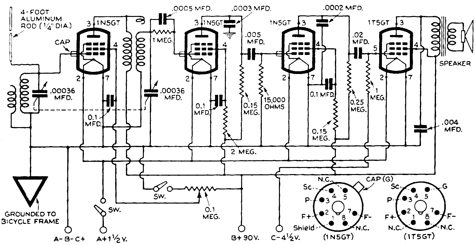
This article by Arthur C. Miller was published on pages 88 to 90 in the book "Radio For The Millions," prepared in 1945 by the Popular Science Monthly staff, but first appeared in "Popular Science Monthly" in April 1940....