
AM-FM-TV RF AMPLIFIER
The universal RF amplifier circuit employs either the BF194 or BF198 transistors, both of which are suitable for high-frequency applications. The circuit is designed to enhance RF signals, making it ideal for various communication tasks, including radio frequency transmission and reception.
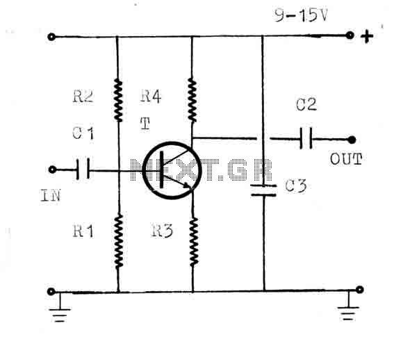
The resistors in the circuit include R1 (22KΩ), R2 (100KΩ), R3 (18Ω), and R4 (1.2KΩ). R1 and R2 form a voltage divider that sets the biasing conditions for the transistor, ensuring it operates within its active region for optimal amplification. R3 serves as a load resistor, helping to convert the amplified current from the transistor into a voltage signal. R4 is used for emitter biasing, stabilizing the transistor's operating point against variations in temperature and transistor parameters.
Capacitors C1 (470pF), C2 (470pF), and C3 (1nF) are crucial for coupling and bypassing in the circuit. C1 and C2 are used for AC coupling, allowing the RF signals to pass while blocking any DC components, thus preventing distortion in the amplified signal. C3 serves as a bypass capacitor, helping to maintain a stable voltage across the transistor by filtering out high-frequency noise.
The use of coaxial cable for connections is essential in RF applications to minimize signal loss and interference. Coaxial cable provides a shielded environment for the signal, reducing the impact of external electromagnetic interference, which is critical for maintaining the integrity of the RF signals being amplified.
Overall, this universal amplifier circuit is versatile and can be adapted for various RF applications, making it a valuable tool in the field of electronics and communication systems. Proper assembly and layout are crucial to ensure the circuit functions as intended, with attention paid to component placement and the use of appropriate shielding techniques.The circuit is a universal amplifier that can amplify any rf signal. You can use the BF194 or the BF198. Make sure you use coaxial cable. Parts: R1=22K R2=100K R3=18 R4=1.2K C1=470PF C2=470PF C3=1NF T= BF194 OR BF198 🔗 External reference
Related Circuits
This is a very simple, low cost, Hi-Fi quality power amplifier. You can build it 5 ways, like it is shown in the table (from 20 W to 80 W RMS). The first thing that you must do, is...
A common collector amplifier circuit structure and its key components are outlined. The composition of the common collector amplifier circuit is fundamentally similar to that of a common emitter amplifier circuit, with two notable exceptions: one is the collector...
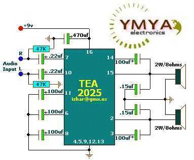
These circuits are based on TEA2025, a monolithic integrated audio amplifier in a 16-pin plastic dual in-line package manufactured by UTC. The circuit includes an internal thermal protector and is designed for portable cassette players and radios. It can...
This is a convenient and straightforward general-purpose 50-watt amplifier. The amplifier features an input for connecting devices such as radios, TVs, or stereo equipment. Additionally, it includes a phono input suitable for connecting record players, guitars, microphones, or other...
A unit which is often very useful, if we need to isolate, in sound circuits, two stage between them. Then we can use this circuit which has an amplified unit, which gain X1, we do not use total negative...
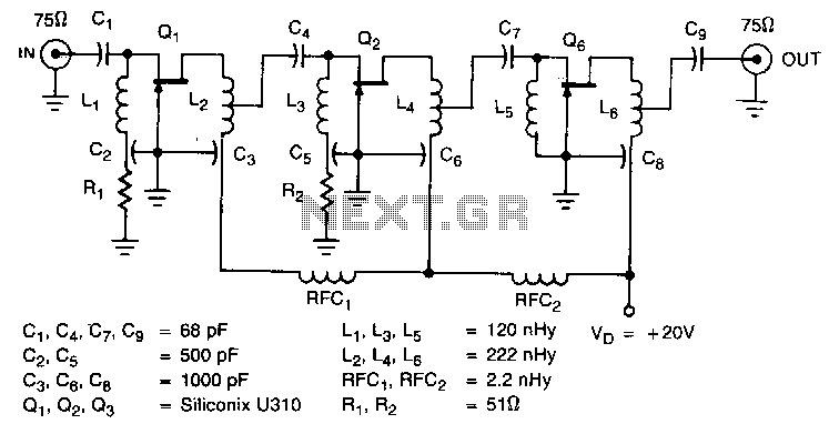
The amplifier circuit is designed for a 225 MHz center frequency, with a 1 dB bandwidth of 50 MHz, low input VSWR in a 75-ohm system, and a gain of 24 dB. Three stages of U310 FETs are utilized...