
Hi-Fi power amplifier with MJ3001 and MJ2501

More: - Before the first "turning on" you must short circuit the inputs of the amp, and put a mA-meter on the output, then turn the amplifier on, and tune the R13 pot, to decrease the DC current on the output, to some µA-s, or in a lucky situation to zero. I was able to decrease it to 10 µA.
This power amplifier is designed to deliver high-fidelity audio output while maintaining a low-cost structure. The amplifier can be configured in five different ways, allowing for output power ranging from 20 W to 80 W RMS, depending on the specific requirements of the application.
Key components include the output transistors, T3 and T4, which are critical for the amplifier's performance. The transistors used, MJ3001 and MJ2501, are known for their reliability and efficiency in audio applications. It is essential to measure the current gain (hfe or β) of these transistors prior to assembly. A mismatch in the hfe values greater than 30% can lead to significant distortion and a lack of clarity in the sound output. It is recommended to use matched pairs of transistors to ensure optimal performance.
Before powering on the amplifier for the first time, it is crucial to take specific precautions to avoid damaging the circuit. The inputs of the amplifier should be shorted, and a milliampere meter should be connected to the output. This setup allows for monitoring of the output current during the initial power-up. Once the amplifier is powered on, the adjustable resistor R13 should be tuned to minimize the DC offset at the output. Ideally, this offset should be reduced to a few microamperes, or in an optimal scenario, to zero. Successful adjustment can result in a DC output current as low as 10 µA, which is acceptable for high-fidelity audio applications.
Overall, this amplifier design provides a straightforward approach to building a high-quality audio amplifier with careful attention to component matching and initial setup procedures, ensuring a clear and accurate sound reproduction.This is a very simple, low cost, Hi-Fi quality power amplifier. You can build it 5 ways, like it?s shown in the table (from 20 W to 80 W RMS). The first thing that you must do, is to measure the end transistors (T3 and T4) amplifying coefficient, the hfe or ?. If their disagreement is bigger than 30 %, the amplifier would not give a clear sound. I used MJ3001 and MJ2501 transistors, and this disagreement was around 5%. - Before the first ?turning on? you must short circuit the inputs of the amp, and put a mA-meter on the output, than turn the amplifier on, and tune the R13 pot, to decrease the DC current on the output, to some uA-s, or in a lucky situation to zero. I was able to decrease it to 10 uA. 🔗 External reference
Related Circuits
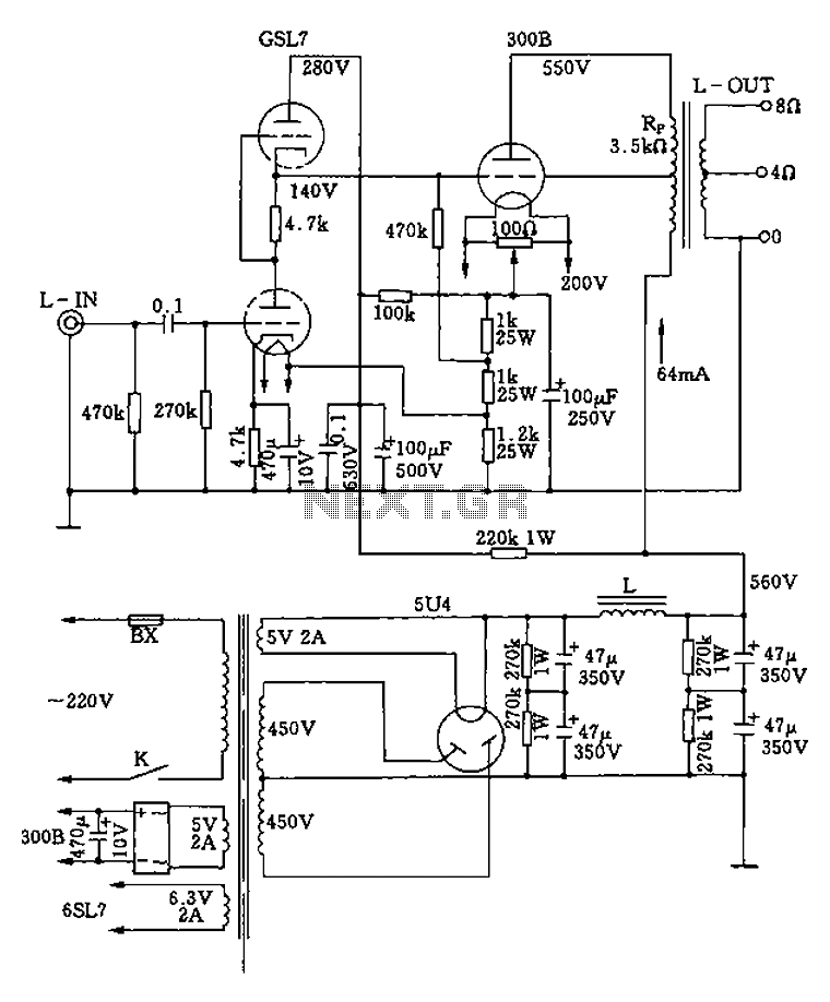
The 300B tube single-ended Class A amplifier circuit is as follows: The 300B tube single-ended Class A amplifier is a high-fidelity audio amplification circuit that utilizes a 300B vacuum tube as the primary amplification element. This design is characterized by...

This is a circuit for an accelerometer amplifier. It is a straightforward circuit. A precision accelerometer requires an inverting mode amplifier since these devices typically output charge. This amplifier converts charges into a voltage output. The circuit presented below...
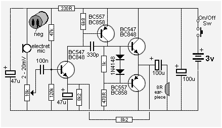
The following circuit presents a Mini Audio Amplifier Circuit Schematic Diagram. Features include a power consumption of less than 3mA, a small output, and the use of a push-pull configuration. The Mini Audio Amplifier Circuit is designed to amplify low-level...
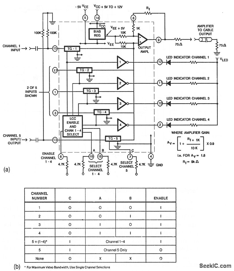
This circuit illustrates a CA3256 switch/amplifier configured for a direct-coupled output. One of four channels can be selected in parallel with channel 5. The analog switches of channels 1 to 4 are digitally controlled by logic. A VEE of...
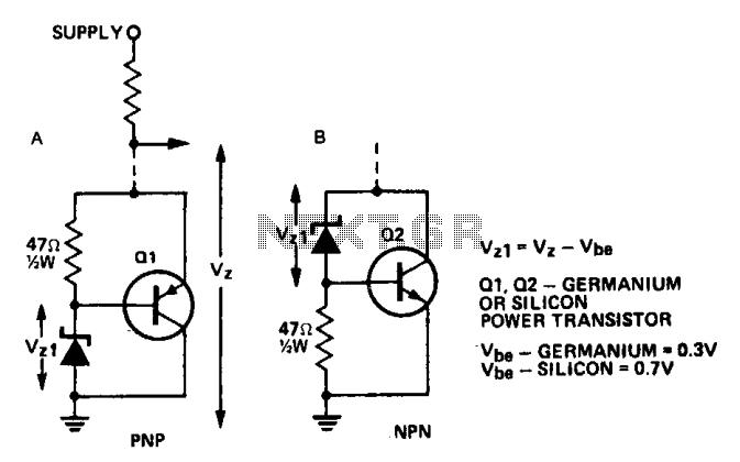
A power transistor can be utilized to supply a high-powered Zener voltage from a low-wattage Zener diode. A 400 mW Zener diode can be employed in applications requiring a 10-watt Zener, or a 1 W Zener can be used...
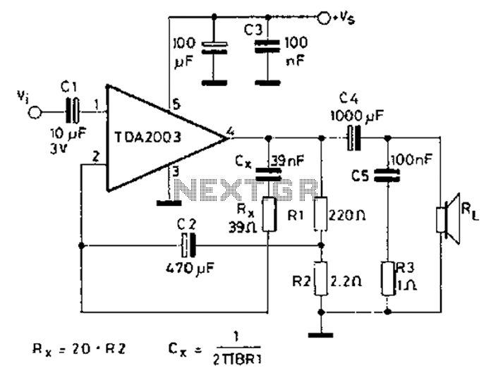
In 2003, the US Trade and Development Agency enhanced the performance of a device maintaining the same pin configuration as in 2002. The agency introduced additional functions in 2002 while ensuring a minimal number of external components, facilitating easy...