
AM Radio Receiver
The AM radio receiver circuit employing the MK484 IC is an efficient design for receiving amplitude modulation signals. The use of a minimal number of components, including resistors with specified values and capacitors, facilitates straightforward construction and troubleshooting. The circuit operates effectively within the specified frequency range, making it suitable for various AM radio stations.
The active antenna enhances reception capabilities, particularly beneficial in areas with weak signals. The design allows for compatibility with untuned wire antennas, thereby increasing its usability in inexpensive radio models and car radios, which often lack sophisticated antenna systems. The circuit's power requirements are modest, enabling it to run off a standard 9V battery, making it portable and convenient for various applications.
In addition to its primary function as an AM receiver, the circuit can be adapted for use in a wireless car alarm system. The integration of transmitter and receiver modules allows for effective communication over FM radio waves, providing a reliable security solution for vehicles. This versatility is a key advantage, as it allows the same basic circuit design to be employed in different applications, from radio reception to vehicle security.
The simplicity of the FM receiver design, which utilizes only a single transistor, underscores the potential for compact and efficient radio circuits. This design is particularly useful for educational purposes, as it demonstrates fundamental radio principles without the complexity of multiple active components. The output configuration allows for easy connection to earphones or amplification systems, catering to various user preferences for audio output.
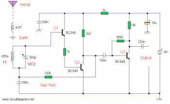
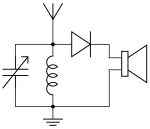
Overall, the circuit design exemplifies a practical approach to radio technology, allowing enthusiasts and beginners alike to explore the fundamentals of radio frequency reception and transmission.Here the AM Radio receiver circuit diagram based on old single IC MK484. Components part list: R9, R10_ 6R8 R6_ 100R R3_ 1K R1_ 4K7 R7_ 5K6 R4_ 10K R2_ 100K R5_ 150K R8_ 820K Pot_ 10K log pot Coil & ferrite bar set C7_ 470p ceramic C, C4, C5, C6_ 470nF monoblock C2_ 100nF. This circuit is a tuned radio frequency (TRF) receiver of the standard AM (amplitude modulation) radio with broadcast frequencies at 550kHz-600kHz. This is a simple and easy to build AM radio circuit which only using two integrated circuits (IC). This circuit works with 9V voltage supply, you could use 9V standard battery to cupply this. This is an active antenna for FM radio receiver, AM radio receiver and SW (shortwave) radio receiver. On the shortwave band this active antenna is comparable to a 20 to 30 foot wire antenna. This circuit is designed to be used on receivers that use untuned wire antennas, such as inexpensive units and car radios.
. This circuit is a wireless car alarm system that is built using two circuit modules, namely modules of transmitter and receiver modules. This circuit works on FM radio waves. Car alarms can be used on vehicles that have a 6-12VDC power supply. You can use the voltage stabilizer if your car power supply is too. This is a very simple FM receiver which build based on one transistor only. No chip or another active component. The output is connected to earphones, you need an amplifier circuit if you want to listen the radio with a loudspeaker.
Part designator Part description C1a, C1b 10 pf, 50 v, ceramic disc capacitor C2 22. 🔗 External reference
Related Circuits
The development of this interface for Echolink took some time. It utilizes the PIC16F84A microcontroller and accepts external DTMF signals from a radio. The latest version, Foxecho-k7, provides complete isolation between the radio and the PC and features automatic...
This is a simple RF receiver mainly for low-distance digital radio receiver application. The analog output of this circuit should be connected to a schmitt-trigger signal conditioning circuit with a proper value capacitor (from collector of T3). L1 for...
A simple audio amplifier application using a TL431 voltage regulator. The amplifier is designed to produce room-filling sound from a standard clear radio equipped with a long-wire antenna and suitable ground. The chip is similar in complexity to a...
A user is seeking assistance with tuning a radio circuit they are building independently for the first time, outside of a classroom setting. The process of tuning a radio circuit involves adjusting various components to ensure proper reception of radio...
This is a simple hardware computer interface and Linux program that can be used to control the most commonly used buttons on any consumer Family Radio Service (FRS) or General Mobile Radio Service (GMRS) radio. There are 22 available...
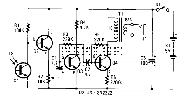
The circuit consists of Q1, a phototransistor that responds to an intensity of amplitude-modulated infrared light source, and a three-stage, high-gain audio amplifier. Transformer T1 is utilized to match the output impedance of the receiver to modern low-impedance (low-Z)...
Warning: include(partials/cookie-banner.php): Failed to open stream: Permission denied in /var/www/html/nextgr/view-circuit.php on line 713
Warning: include(): Failed opening 'partials/cookie-banner.php' for inclusion (include_path='.:/usr/share/php') in /var/www/html/nextgr/view-circuit.php on line 713