
AM Radio Receiver Circuit
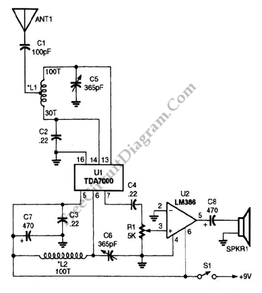
The AM radio receiver circuit is designed to capture amplitude-modulated (AM) signals and convert them into audible sound. The core of this circuit is an FM IC chip, which is typically optimized for frequency modulation but can be adapted to receive AM signals through specific configurations.
The circuit begins with the antenna, which collects the incoming radio waves. The signals are then fed into a front-end amplifier, which enhances the weak signal strength for better processing. Following amplification, the signal enters the FM IC chip, which has been configured to demodulate AM signals. This involves detecting the amplitude variations in the signal, which correspond to the audio information being transmitted.
Hand-wound coils play a crucial role in tuning the circuit to the desired AM frequency. These coils are inductors that, together with capacitors, form a resonant LC circuit. By adjusting the number of turns in the coil and the value of the capacitor, the circuit can be tuned to specific frequencies within the AM bandwidth, typically ranging from 530 kHz to 1700 kHz.
The output from the FM IC chip is an audio signal that is still relatively weak, requiring further amplification. This is achieved through a power amplifier stage, which drives a speaker or an earphone, allowing the audible sound to be heard.
In summary, this AM radio receiver circuit combines an FM IC chip with hand-wound coils to effectively receive and demodulate AM signals, providing a functional and efficient design for AM radio applications.AM radio receiver circuit employing FM IC chip as the main component. This AM radio receiver circuit uses hand-wounded coils to tune the frequency at AM bandwidth 🔗 External reference
Related Circuits

This circuit is designed for differential analog circuit switches. The FM1208 monolithic dual differential multiplexer is utilized in applications where the RDS (ON) must be closely matched. The RDS (ON) for the monolithic dual multiplexer operates with a precision...
A display tube utilizing a constant current circuit to ensure a steady flow through the tube. The display tube operates on the principle of maintaining a constant current to achieve consistent brightness and performance. The circuit typically comprises a current...
This small circuit transmitter processes audio signals from a sound table or microphone, as well as video signals from a camera, DVD, or video cassette. It has a composite video output, allowing direct transmission from a computer over a...
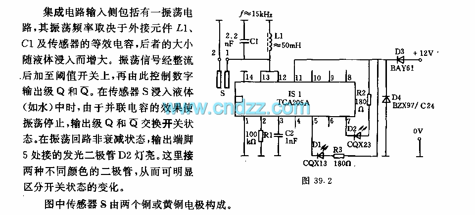
The integrated circuit input side contains an oscillating circuit, where the oscillation frequency is determined by the external components L1, C1, and the sensor's equivalent capacitance. The equivalent capacitance increases as the sensor is immersed in liquid. The oscillating...
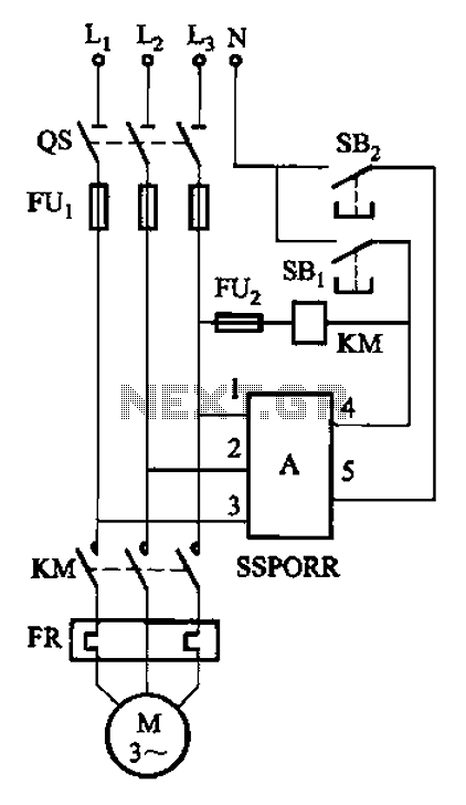
The solid-state phase failure relays for three-phase AC phase failure monitoring, protection, and control of new devices are referred to as SSPORR. This module consists of a five-terminal semiconductor configuration. Terminals 1, 2, and 3 serve as the three-phase...
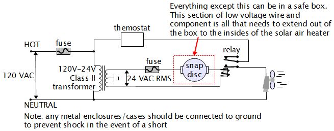
For various experiments, such as solar air heaters, an automatic fan activation and deactivation system is required. A straightforward solution is to use a bimetal snap disc thermal sensor. This sensor functions as a switch that closes when a...
Warning: include(partials/cookie-banner.php): Failed to open stream: Permission denied in /var/www/html/nextgr/view-circuit.php on line 713
Warning: include(): Failed opening 'partials/cookie-banner.php' for inclusion (include_path='.:/usr/share/php') in /var/www/html/nextgr/view-circuit.php on line 713