
temp control circuit

The bimetal snap disc thermal sensor operates based on the principle of thermal expansion. It consists of two different metals bonded together, which expand at different rates as temperature increases. When the temperature exceeds the setpoint, the bimetal disc bends, causing it to close the circuit and activate the fan. Conversely, when the temperature drops below the lower setpoint, the disc returns to its original shape, opening the circuit and turning off the fan. The selection of the activation and deactivation temperatures can be adjusted based on the specific application requirements, providing flexibility in managing the heating process.
In the context of solar air heaters, the proper placement of the snap disc sensor is critical for accurate temperature readings. It should be positioned in an area where it can effectively monitor the air temperature being heated by the solar collector. The fan used in conjunction with the sensor should be rated for the appropriate voltage and current, ensuring it can handle the operational demands without overheating.
For installations requiring lower voltage operations, a transformer can be utilized to step down the voltage from the mains supply to the desired level, ensuring safety and compliance with electrical standards. The transformer should be rated according to the load requirements of the fan and any additional components in the circuit.
In summary, the integration of a bimetal snap disc thermal sensor with a fan in a solar air heater application provides an efficient and automated solution for temperature control. Proper component selection, wiring, and installation practices are essential for ensuring safety, reliability, and optimal performance of the system.For a few experiments such as solar air heaters, I needed a automatic turning on and off of a fan. Probably the simplest way to do this is with a bimetal snap disc thermal sensor. A bimetal snap disc thermal sensor is basically a switch that closes when a specific high temperature is reached and opens when a specific lower temperature is reached. That way, by connecting in a fan in series with the switch, the fan would turn on when the high temperature is reached and off then the lower temperature is reached. They are also referred to as snap disk controllers and snap switches. In the UK they`re often referred to as thermostats or bimetalic thermostats and can be found at Sinolec Components - or RS Components - uk.
rs-online. com. Make sure you get one where the temperature that turns on the fan (the switch closes) is higher than the temperature that turns off the fan (the switch opens. ) Most people use ones that turn on at 110F and off at 90F. WARNING: Many of the following photos and videos show Romex wire being used for the length of wire extending into the solar air heater to the snap disc sensor.
These were used in experimental situations. Consider using teflon insulated wire instead. Why If it`s a sunny day and no air is being circulated through the heater because the house is already hot enough then the temperature where the wire is inside the solar air heater may get over 200F (93C). This may be over the wire`s insulation`s rating. If the insulation melts it may cause a short circuit and result in a fire. The following videos give step-by-step details for making the AC circuit. The first video introduces the snap disc sensor, tests a prototype circuit and shows how to determine the size of fuse needed for your fan or blower.
It`s especially useful for anyone not familiar with electronics. This next video wires up the actual circuit in a safe manner (safety is imporant here since it`s being plugged into the household wiring), assembles it all in a nice box, puts it in the actual solar air heater and does a quick test. If your room is already hot enough then you don`t want your solar air heater to provide more hot air.
This can be controlled by adding a thermostat to the circuit. The thermostat is basically another switch that opens when the room is hot enough and closes when the room needs more heat. The following diagram has the themostat added. The snap disc sensor is located in the solar air heater. Using the above schematic, the sensor has 120VAC across it. It may be preferable to have lower voltage wiring in this area and for that the following schematic can be used.
All other circuitry can be housed in a box that is mounted to the blower/fan enclosure and so all wiring there can have the higher 120 volts AC while only lower voltage 24 volts AC wires would extend out to the location of the snap disc sensor. 🔗 External reference
Related Circuits
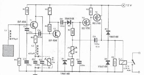
A simple proximity detector can be created using this electronic circuit. This circuit responds to the presence of a conductive object within a specific range. The sensitivity of the circuit can be adjusted with potentiometer P1 to achieve the...
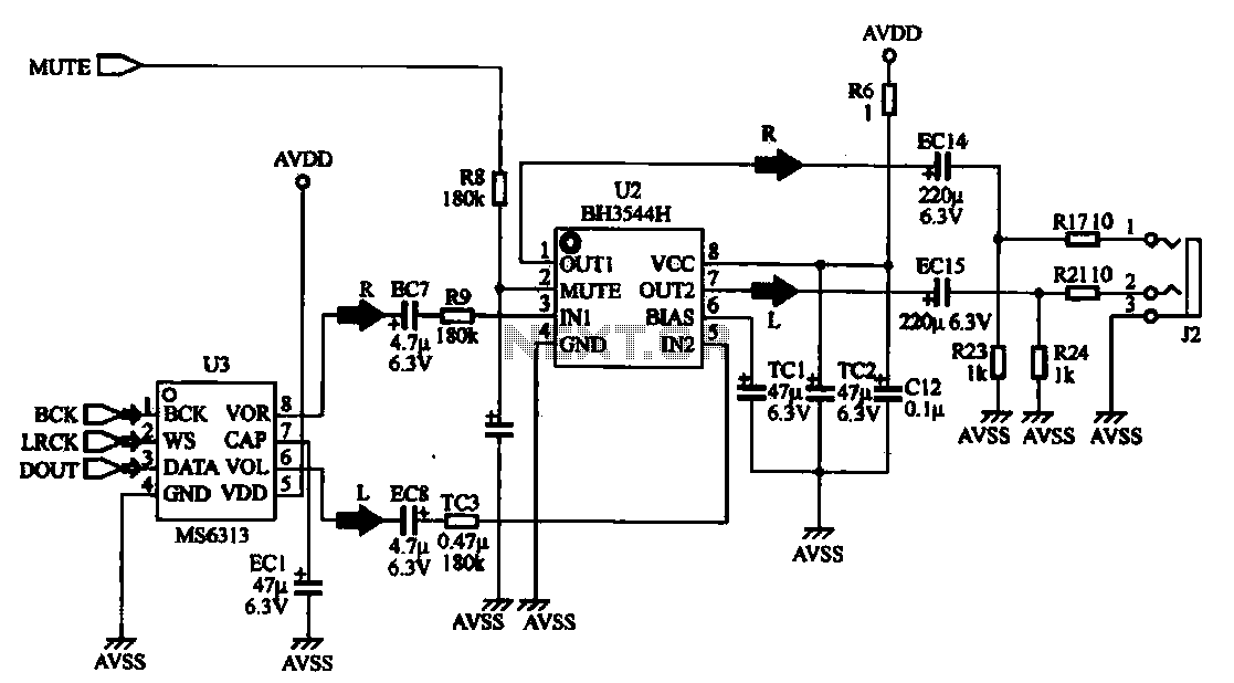
The MP4 audio circuitry consists of audio D/A converters and an audio amplifier combination circuit. This design features a straightforward circuit layout, making it suitable for integration into compact MP4 digital devices. The MP4 audio circuitry is designed to efficiently...

This is an analog TV transmitter. Sound modulation is of the FM type with a 5.5 MHz carrier frequency, and video transmission follows the PAL standard. The frequency can be adjusted using capacitor C5, allowing tuning from 54 to...
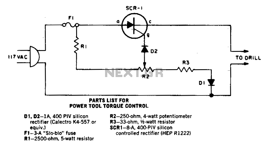
As the speed of an electric drill decreases due to loading, its torque also diminishes. A compensating speed control circuit restores power to the motor. When the drill slows down, the back voltage developed across the motor—connected in series...
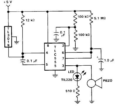
This door open alarm electronic project is designed using a linear hall effect device and a 555 timer circuit. The project utilizes the TL3103 linear hall effect device for detecting the angle of rotation. The TL3103 is positioned within...
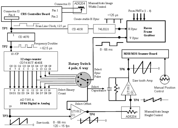
Before building the control circuit, it is essential to understand the function of each component. The schematic below illustrates only the basic functions. The CRS Controller board generates the key synchronization signal, known as the Scan Line Clock (SLC),...