
Ammeter with six decade range
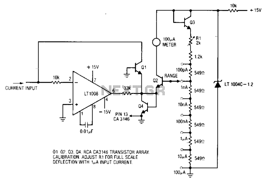
The ammeter circuit is designed to provide precise current measurements over a broad dynamic range, from picoamperes (pA) to microamperes (µA). This capability is achieved without the necessity of using high-value resistive components, which can introduce additional costs and potentially compromise measurement accuracy due to thermal and noise effects.
The primary components of the ammeter include two operational amplifiers (Q1 and Q2) configured to form a differential amplifier. This configuration allows the circuit to effectively measure small currents while minimizing the influence of offset voltages. The offset voltage between Q1 and Q2 is critical, especially at higher current levels (100 µA), where even minor discrepancies can lead to significant errors in measurement.
At lower current levels, specifically around 100 pA, the performance of the ammeter is predominantly affected by the inverting bias current of the LT1008 operational amplifier. This bias current can introduce noise and drift, impacting the accuracy of low current measurements. Therefore, careful consideration of component selection and circuit layout is essential to mitigate these effects.
The circuit may also incorporate additional features such as filtering and calibration adjustments to enhance measurement reliability. By ensuring that the operational amplifiers are operated within their optimal ranges and minimizing external interference, the ammeter can achieve high precision across its specified current range.The Ammeter measures currents from 100 pA to 100 µ without the use of expensive high value resistors. Accuracy at 100 µ is limited by the offset voltage between Ql and Q2 and, at 100 pA, by the inverting bias current of the LT1008. 🔗 External reference
Related Circuits
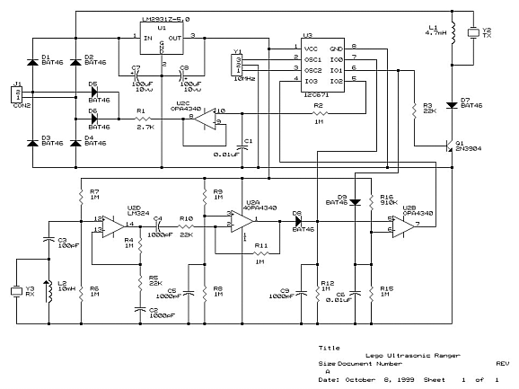
The Panasonic transducers are no longer available, but the design remains interesting as an example. J1 connects to the RCX. D1 to D4 create a bridge rectifier to obtain local power from the RCX, which is stored on C7...
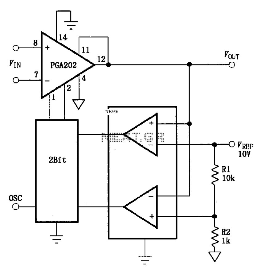
The automatic range switching circuit consists of PGA202, comparators, and counters, as illustrated in the figure. The comparator at the output compares VOUT with VREF. When VOUT exceeds 10V, the comparator generates a low signal, causing the up/down counter...
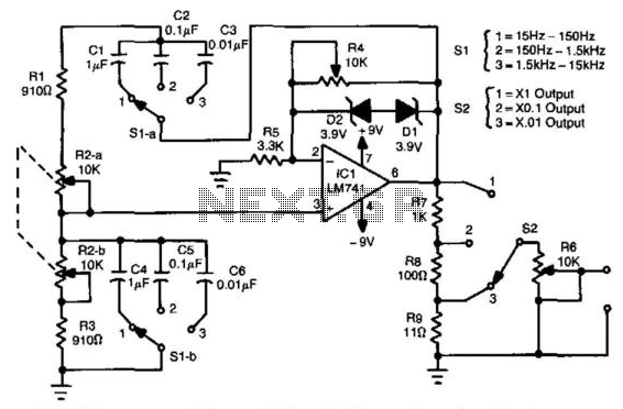
In this circuit, an LM741 operational amplifier drives a Wien-bridge network utilizing two zener diodes as an amplitude limiter. Range selection is performed by a switch that selects between capacitors (C1 through C6), while tuning is achieved using a...
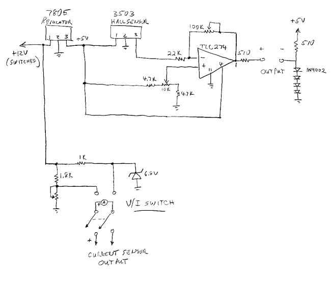
The sprite, which is experiencing an additional electrical load from an electric cooling fan, is barely maintaining battery charge. To address this issue, an electronic voltage regulator is planned; however, monitoring the charging process is essential before making any...
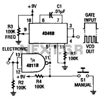
A CD4046 can be gated either with a switch or electronically, as shown in the figure. The frequency range of this circuit is up to 1.5 kHz; use another capacitor C1 for higher frequencies. The CD4046 is a versatile phase-locked...
The 1N4001 is a 1 Amp silicon rectifier with a voltage range of 50 to 1000 volts. It features guaranteed high-temperature soldering, high current capability, a diffused junction, low reverse leakage, and utilizes a void-free molded plastic technique for...