
Automatic range switching circuit diagram PGA202
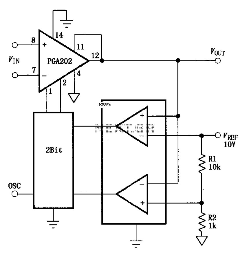
The automatic range switching circuit is designed to optimize the gain of the programmable gain amplifier (PGA202) based on the output voltage (VOUT) in relation to a reference voltage (VREF). This circuit employs voltage comparators to monitor VOUT continuously. When VOUT surpasses the threshold of 10V, the comparator's output transitions to a low state, signaling the up/down counter to decrement the gain of the PGA202. This decrement is implemented through a 2-bit binary code sent to the A0 and A1 pins of the PGA202, effectively reducing the amplifier's gain to prevent saturation and maintain signal integrity.
In contrast, when VOUT drops to approximately 0.909V, which is derived from the voltage divider formula [1k/(1k + 10k)] * 10V, the comparator's output switches to a high state. This change instructs the up/down counter to increment the gain of the PGA202, again using a 2-bit binary code directed to the A0 and A1 pins. The ability to dynamically adjust the gain based on VOUT ensures that the circuit can accommodate a wide range of input signal amplitudes, thus enhancing the performance and adaptability of the system in various applications.
The design of this circuit necessitates careful consideration of component specifications, such as the response time of the comparators and the resolution of the up/down counter, to ensure that the switching occurs promptly and accurately. Additionally, the choice of resistors in the voltage divider impacts the threshold levels and, consequently, the overall performance of the automatic range switching mechanism. This circuit is particularly useful in applications where signal amplitudes may vary significantly, requiring robust gain control to maintain optimal performance. As shown in FIG grounds PGA202 and comparators, counters constitute automatic range switching circuit. The circuit at the output of the comparator compares VOUT when VOUT VREF 10V, the comparator outputs down signal, up/down counter output 2Bit coding PGA202 of A0, A1 side to make the PGA202 gain decrease; when VOUT [1k/(1k + 10k )] 10V 0.909V, the comparator outputs l signal, up/down counter output 2Bit coding to A0, A1 end PGA202 and PGA202 make the gain increases.
Related Circuits
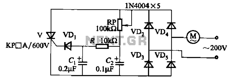
The circuit illustrated in Figure 3-11 employs a unidirectional thyristor control mechanism. An adjustable potentiometer, designated as RP, is utilized to continuously modify the motor speed. The circuit utilizes a unidirectional thyristor, also known as a silicon-controlled rectifier (SCR), which...
Figures (a) and (b) illustrate two basic oscillator circuits operating at 2 MHz. The circuit design allows for adjustment of the optimal operating point through testing. The two oscillator circuits depicted in the figures utilize different configurations to achieve stable...
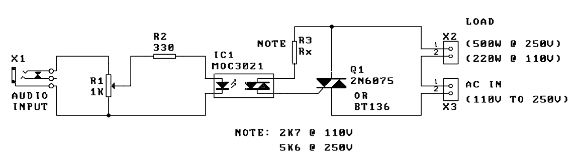
A music-to-light modulator is a circuit which controls the intensity of one or more lights in response to an audio input. The problem in older circuits is that there was a direct electrical connection between the lights using mains...

This circuit is particularly beneficial for hobbyists using a breadboard to experiment with ideas, as well as those employing a simple homemade DC power supply that consists of a transformer, rectifier, smoothing capacitor, and protective fuse, specifically one lacking...
If the transmitter stick-potentiometer delivers a voltage about 2 - 3 V, this circuit will be suitable. If you want to avoid using the battery cable (supplying Vcc for IC1 and -2), you can use a separate 5V supply...
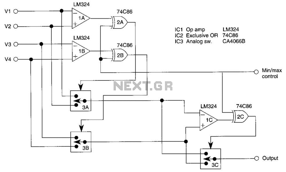
This circuit outputs the maximum or minimum of four input voltages, V1, V2, V3, and V4. Each of these input voltages ranges from 0 to 5 V. The output of the circuit is the maximum of V1, V2, V3,...
Warning: include(partials/cookie-banner.php): Failed to open stream: Permission denied in /var/www/html/nextgr/view-circuit.php on line 713
Warning: include(): Failed opening 'partials/cookie-banner.php' for inclusion (include_path='.:/usr/share/php') in /var/www/html/nextgr/view-circuit.php on line 713