
Amp Circlotron
The simplified schematic of a circlotron power output stage includes floating power supplies represented as B1 and B2, with C serving as the bias supply. Each power supply's negative terminal connects to one side of the output transformer, necessitating a separate pair of power supplies for each channel in a stereo amplifier. Commercial stereo amplifiers typically utilized a power transformer with five B+ windings: two for each channel and a fifth for the preamp, drivers, and bias supply. Notably, the bias supply is often derived from the B+ winding or a tap on it, eliminating the need for a separate bias winding. The positive terminal of the bias battery is grounded, allowing a single supply to serve both channels.
Each tube operates as a cathode follower, providing a gain slightly less than unity. For a 50-watt amplifier, the driving voltage exceeds what an air conditioner requires to operate. Generating such high audio voltage at low power levels without introducing significant distortion is challenging. There is some debate regarding the use of the term "cathode follower" to describe the tube configuration in this circuit, as critics argue that the plate receives a signal out of phase with the grid and cathode voltage, which is not characteristic of a typical cathode follower. However, this phase relationship is a result of the circular configuration, and if feasible, it would not be part of the design.
Despite the variation in plate voltage, each tube continues to function as a cathode follower, maintaining a gain slightly less than unity, with the cathode tracking the grid voltage. Theoretically, the optimal load impedance is one-fourth of the recommended impedance for the same tubes in a conventional push-pull configuration. Consequently, the output transformer requires less inductance, resulting in fewer turns in the primary winding, which facilitates achieving low-end frequencies down to 20 Hz. Fewer turns also reduce stray capacitance, enhancing high-frequency performance. The self-resonant frequency will be elevated, simplifying the compensation of the global feedback loop if implemented.
In contrast to conventional push-pull amplifiers, where one tube enters cutoff, leading to current flowing through only half of the primary winding, this design applies drive to the entire primary winding continuously. When V2 is in cutoff, electrons flow from the top of the transformer to the cathode of V1, through V1 to the positive terminal of B1, exiting its negative terminal to the bottom of the transformer, and completing the circuit. Conversely, when V1 is in cutoff, the electron current path is from the bottom of the transformer, through V2, B2, and down through the transformer, utilizing the entire primary winding. With the center tap grounded, the only other ground is connected to the grids, which are high impedance points and do not participate in current flow. This characteristic enables the transformer to have one-fourth the impedance compared to that of a conventional push-pull circuit. The absence of DC in the output transformer primary eliminates core saturation issues, provided the tubes are well-matched.It`s a power amplifier configuration that was developed in the 1950s. It is called a circlotron because the original idea diagram was drawn as a circle. The best I can do with my graphics program is to show it as a bridge. It`s promise is very low distortion. It`s cost is a total of 3 power supplies, none of them connected in common. Some amplifiers were commercially produced using this circuit. They were high end units because of the high cost to produce. The circuit never caught on because the design had shortcomings which caused it to be unreliable. Here is the simplified schematic of a circlotron power output stage. B1 and B2 aren`t really batteries but represent totally floating power supplies. The battery marked C is the bias supply. Because each power supply has its negative terminal connected to one side of the output transformer, each channel of a stereo amplifier requires its own pair of power supplies. Commercial stereo amplifiers would have been made with a power transformer having 5 B+ windings. Two for each channel and the fifth for the preamp, drivers, and bias supply. Note: The bias supply is usually stolen from the B+ winding, or a tap on it, so a separate bias winding was not necessary.
The positive of the bias battery is grounded so a single supply could have been used for both channels. Each tube is working as a cathode follower so its gain is a little less than unity. For a 50 watt amplifier the driving voltage is more than your airconditioner needs to run. It is not easy to develop this much audio voltage, even at low power, without introducing a lot of distortion.
Some readers have objected to the use of the term "cathode follower" to characterize the tube configuration in this circuit. They argue that the plate is supplied a signal which is out of phase with the grid and cathode voltage which is not the nature of a cathode follower.
However, This is a byproduct of the circular configuration and if it were possible would not be a part of the design. In spite of the plate voltage variation each tube still behaves as a cathode follower, having a gain of slightly less than unity and the cathode following the grid voltage.
Theoretically, the optimum load impedance is 1/4 of the recommended impedance for the same tubes in a conventional push-pull connection. The output transformer will need less inductance so the primary will have fewer turns. This makes it easier to get the low end down to 20 cycles. Fewer turns means less stray capacitance and that will give the transformer a better high end. The self resonate frequency will be higher which makes it easier to compensate the global feedback loop if one is used.
Also, the drive is applied to the whole primary winding all the time. Unlike a conventional push-pull amplifier. In a class AB push-pull amplifier when one tube goes into cutoff, the instantaneous current is flowing from the center-tap to the plate of the conducting tube through only half of the primary. If you look at the diagram above you can see that when V2 is in cutoff, electrons flow from the top of the transformer to the cathode of V1, through V1 to the positive of B1, out of its negative, to the bottom of the transformer, and up through it to complete the circuit.
When V1 is in cutoff, the electron current path is from the bottom of the transformer, through V2, B2 and down through the transformer. This uses the entire primary winding. While the center tap is grounded the only other ground is to the grids which are high impedance points and are not involved in the current flow.
This is why the transformer can have 1/4 of the impedance of that for a conventional push-pull circuit. No DC in the output transformer primary means that core saturation is never a problem, unless the tubes are poorly matched.
Without any DC t 🔗 External reference
Related Circuits
This Class A amplifier utilizes a 12AU7-based valve preamp, delivering exceptionally pure sound quality. Although distortion levels are unknown, the amplifier exhibits a fine grain and delicately textured audio output. With an output of only one watt, it requires...
For the 60W amplifier, a nominal (full load) supply of +/- 35V is required, so a 25-0-25 secondary is ideal - however, see Updates, below. The circuit for the supply is shown below, and uses separate rectifiers, capacitors and...

For high-impedance (7,500 ohms) applications, this amplifier will provide a voltage gain of approximately -gm/ZL, where ZL is the load impedance in ohms and gm is approximately 12 x 10^-3 for the 40673 FET. The G2 voltage can be...
The original radio circuitry has been transformed into a block diagram representation. The electrical schematic is illustrated in Figure 1-27, which depicts a typical single-tube amplifier of Group A. One figure represents the audio amplifier circuit for the original...
The LC72146 is a Phase-Locked Loop (PLL) Frequency Synthesizer LSI circuit designed for electronic tuning in car stereo systems. This component facilitates the development of high-performance, multifunctional electronic tuning systems across VHF, MW, and LW bands. It is manufactured...
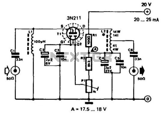
This RF amplifier features a wide bandwidth and dynamic range. It provides a gain of 10 dB, with a noise figure of less than 5 dB. The third-order intercept point (IP3) is -40 dB at an output of +22...