
Making small tube amplifier 01
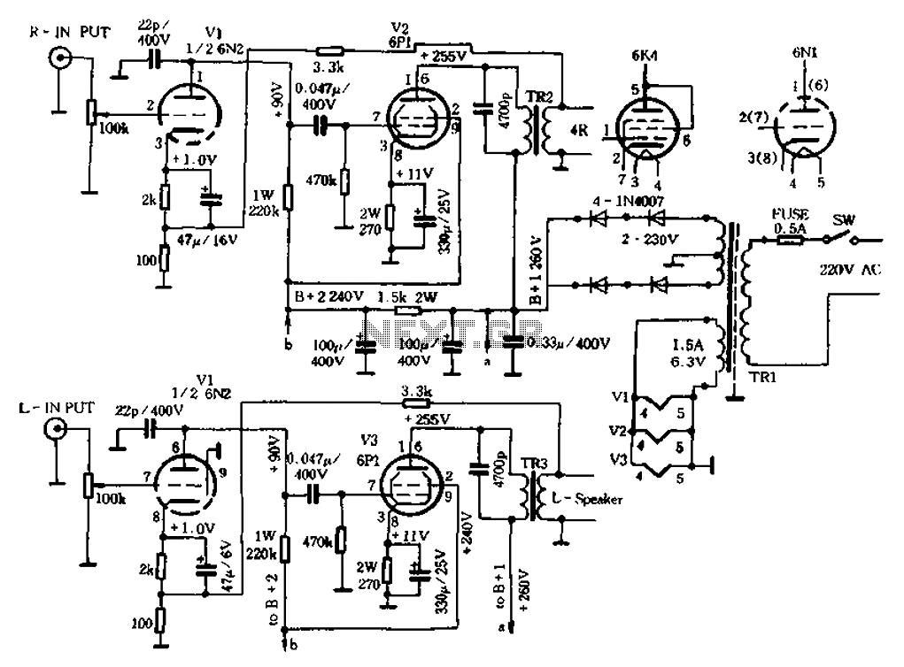
The described circuit is a single-tube audio amplifier, typical of Group A configurations, which are known for their linear amplification characteristics. The 6P1 tube serves as the core amplification element, providing a significant gain while maintaining audio fidelity. The output transformers are crucial for impedance matching and signal transfer to the speaker load, ensuring that the audio signal is effectively transmitted without distortion.
In the schematic, various resistive and capacitive elements are included to form necessary filtering and biasing networks. The choice of a 1/2W power rating for resistors suggests a design that balances power handling with efficiency, suitable for low to moderate power applications typical of audio amplifiers. The omission of the capacitor circuit from the original design indicates a simplification aimed at reducing component count and potential points of failure, while still achieving the desired audio performance.
The audio input section is designed to accommodate various external audio sources, such as VCD players or tape decks, allowing for versatile usage of the amplifier. The ability to connect to different audio sources enhances the functionality of the radio, making it a multi-purpose audio device. The design reflects a practical approach to audio amplification, focusing on essential components to deliver quality sound reproduction.After the original radio with guts shown transformed into a block diagram of the machine. Electrical schematic shown in Figure 1-27, which is a typical type of tube Group A sin gle-tube amplifier. A figure is the original radio channel audio amplifier circuit, and the other sound channel audio amplifier is increased all the way, the increase in the meta element is tube 6P1 and output transformers, as well as some resistive and capacitive elements, element costs 40 yuan. Capacitor circuit with the original Dong was omitted, the remaining elements of the numerical value by icon replacement.
In addition to resistance power has marked, are selected 1/2W. Audio input can be inserted VCD players, tape deck, to close radios tuner.
Related Circuits
The signal from a microphone is too weak for a standard line input. This low-noise DC-coupled microphone amplifier provides a solution for anyone who wants to amplify the microphone signal effectively. A low-noise DC-coupled microphone amplifier is designed to enhance...
A microphone amplifier designed for use with either Electret Condenser Microphone (ECM) inserts or dynamic inserts, constructed with discrete components. The preamplifier circuit is self-stabilizing and sets its quiescent point at approximately half the supply voltage at the emitter...
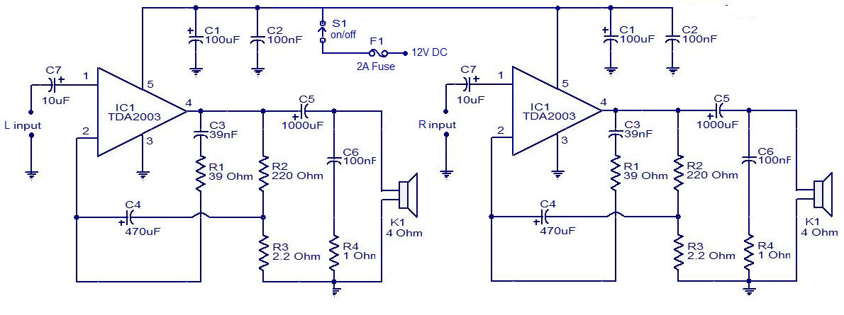
The circuit is easy to construct. The TDA2003 is an integrated radio amplifier from ST Microelectronics that features short circuit protection for all pins, thermal protection, low harmonic distortion, and low crossover distortion. In the circuit provided, the TDA2003...
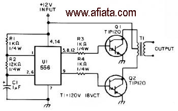
The first section of the 555 timer is configured as an astable oscillator, with R2 and C1 determining the frequency. The output is accessible at pin 5. The second section functions as a phase inverter, with its output available...
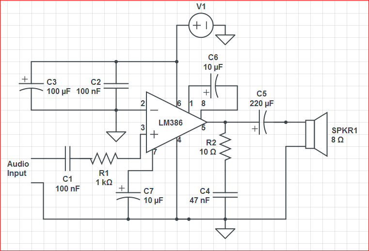
Initially, the circuit was connected to a 9V battery, which registered approximately 8.3 volts on a multimeter, within the operating voltage range for the LM386 as indicated in its datasheet. The output was characterized by significant noise, including crackling...
This circuit is mainly intended to provide common home stereo amplifiers with a microphone input. Using a stereo microphone the circuit must be doubled. In this case, two separate level controls are better than a dual-ganged stereo potentiometer. Low...
Warning: include(partials/cookie-banner.php): Failed to open stream: Permission denied in /var/www/html/nextgr/view-circuit.php on line 713
Warning: include(): Failed opening 'partials/cookie-banner.php' for inclusion (include_path='.:/usr/share/php') in /var/www/html/nextgr/view-circuit.php on line 713