
Amplifier circuit diagram tda1521
The TDA1521A is a versatile and efficient audio amplifier integrated circuit, ideal for applications where space and component count are critical. Its design allows for straightforward integration into various audio systems, particularly portable devices. The amplifier's architecture supports a dual power supply configuration, which significantly improves audio fidelity by eliminating coupling capacitors that can affect sound quality. This configuration is particularly advantageous for achieving a robust bass response, which is often a limitation in low-power audio systems.
In single supply applications, careful attention must be paid to the placement of the power supply filter capacitor. This capacitor should be positioned as close to the power pins of the TDA1521A as possible to minimize inductive effects and stabilize the power supply, thereby enhancing performance and reducing the likelihood of oscillation. The layout of the PCB should consider the thermal characteristics of the circuit; the TDA1521A can generate significant heat under load, necessitating adequate heat dissipation measures. The recommended heat sink dimensions ensure that the device operates within safe thermal limits, preventing damage and ensuring longevity.
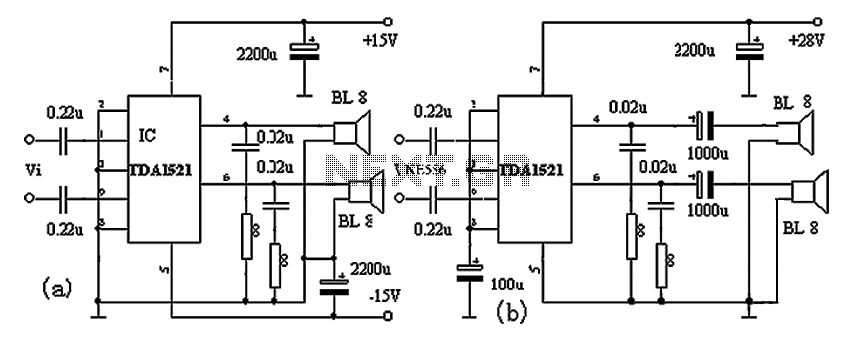
For optimal performance, the circuit should also include proper bypass capacitors near the power supply pins to filter out high-frequency noise that could interfere with audio performance. Additionally, the layout should minimize loop areas in the signal paths to reduce susceptibility to electromagnetic interference. Overall, the TDA1521A amplifier circuit exemplifies a balance of simplicity, efficiency, and high-quality audio output, making it an excellent choice for a wide range of audio applications. As shown with the production of hi-fi amplifier IC TDA1521A amplifier circuit having fewer external components, without debugging, mounted on a ring characteristics. Homemade s uitable for Walkman power connection, or for the transformation of low-powered computer speakers. TDA1521A using nine-pin single in-line plastic package, with output power, two-channel gain difference is small, the speaker no switch machine impact sound and reliable thermal overload and short circuit protection features. TDA1521A When both with positive and negative power supply can also be a single power supply, the circuit schematic are shown in Figure 1 (a), (b) dual power supply, eliminating the need for two audio output capacitance, high bass sound better.
Single supply, power supply filter capacitor should be as close to the power terminal of the integrated circuit, the internal circuit to avoid self-excited. Must give manifold mounted on a heat sink to power test tone production, or easy to damage the manifold.
Radiating plate can not be less than 200 100 2mm3.
Related Circuits
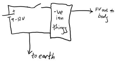
This article demonstrates how to create a simple yet effective static electricity generator. This device enables the user to carry a constant static charge on their body and discharge it onto anything grounded or of opposite polarity. The generated...
This hybrid circuit uses a mixture of transistors, an IC and a relay and is used to automatically open or close a pair of curtains. Using switch S3 also allows manual control, allowing for curtains to be left only...
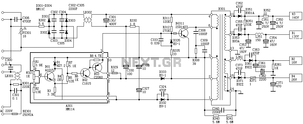
Oscillation: The positive terminal voltage of C310 is approximately 300V. The resistors R311 and R312 are connected to the switch BG311 at the B pole, while the B301 winding via the switching transformer (4) and (6) is connected to...
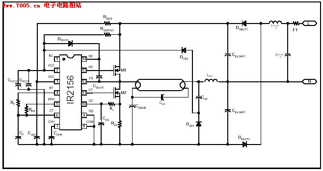
The IR2156 provides a cost-effective solution for fluorescent electronic ballasts. It integrates features such as lighting tube error protection and a programmable working frequency, which includes warm-up, lighting, and continuous operation of the ballast. The IR2156 is a highly integrated...
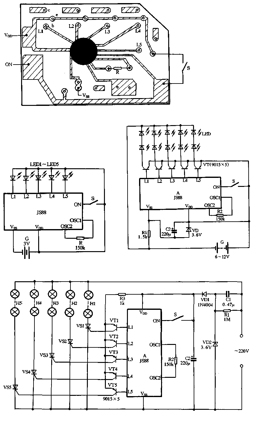
Figure 2-39 illustrates a typical application circuit for the JS88 manifold, which includes an oscillation resistor (R) that allows for fine-tuning of the water flicker frequency. When switch (S) is closed, components L1 to L5 sequentially output low signals...
Can be directly connected to CD players, tuners and tape recorders. Simply add a 10K Log potentiometer (dual gang for stereo) and a switch to cope with the various sources you need. Q6 & Q7 must have a small...
Warning: include(partials/cookie-banner.php): Failed to open stream: Permission denied in /var/www/html/nextgr/view-circuit.php on line 713
Warning: include(): Failed opening 'partials/cookie-banner.php' for inclusion (include_path='.:/usr/share/php') in /var/www/html/nextgr/view-circuit.php on line 713