
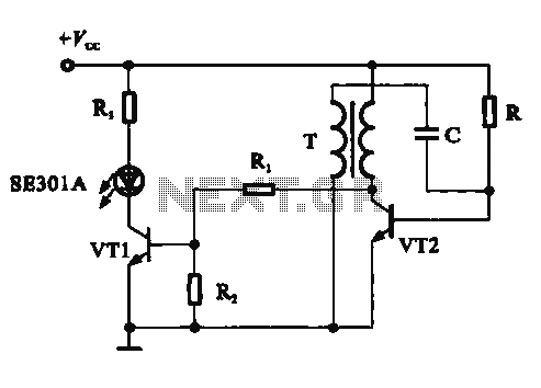
Amplifier input signal overdrive auto-protection
The described circuit functions as a protective mechanism for signals that exceed the standard operational threshold before reaching an amplifier. The key component utilized in this design is a transistor, which serves as a substitute for the more traditional zener diode. This substitution is significant as it allows the circuit to effectively manage higher input voltages, specifically those above 1 volt r.m.s., without introducing distortion to the signal.
The circuit's design is notably efficient, as it minimizes the component count by eliminating the need for additional elements such as potentiometers and voltage dividers. This simplification not only reduces the complexity of the circuit but also enhances reliability by decreasing the number of potential points of failure.
The performance specifications indicate that the circuit maintains a total harmonic distortion (THD) of 0% at output levels up to 700mV r.m.s. This is a critical parameter for audio applications, as it ensures that the output signal remains true to the input signal within this range. For output levels exceeding 700mV r.m.s. and approaching 1V r.m.s., the total harmonic distortion is still impressively low at 0.02%. This level of distortion is acceptable for high-fidelity applications, ensuring that the integrity of the audio signal is preserved even at higher levels.
In summary, this circuit is designed to protect amplifiers from overdriven signals while ensuring minimal distortion, thereby providing an effective solution for audio signal management. The use of a transistor not only simplifies the design but also enhances the performance characteristics of the circuit.That circuit protects the overdriven signals going into an amplifier. Instead of a zener diode we use a transistor. That way we ensure that the above the ordinary input voltages ( 1 volt r.m.s.) can be acheaved without distortion. Also the use of a transistor limits the number of components used in this schematic. You don't need any potentiometers or voltage dividers. The total distortion at the output until 700mV r.m.s. is 0%. Above that until 1V r.m.s. the total harmonic distortion can be 0.02%. 🔗 External reference
Related Circuits
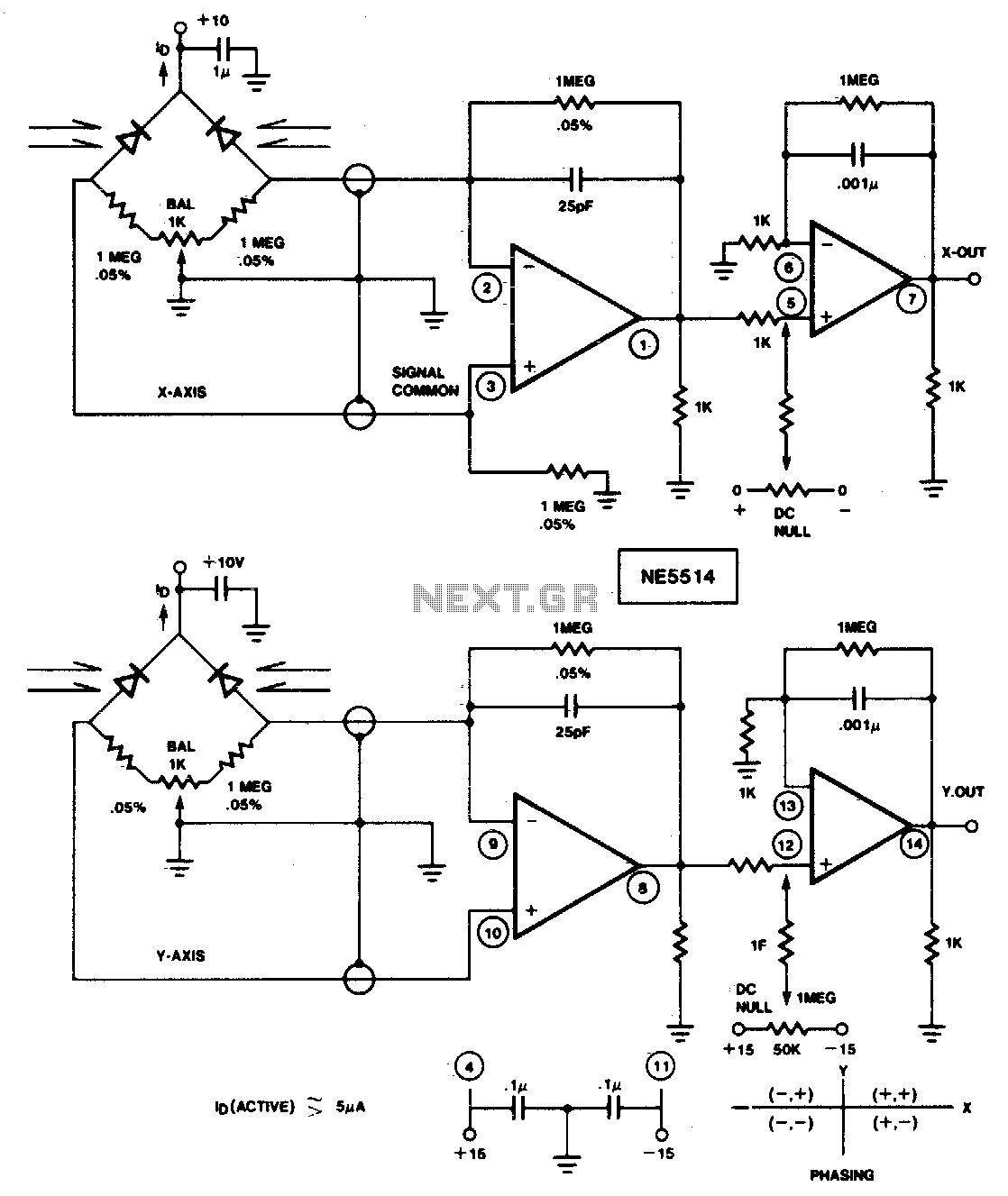
This circuit is designed to detect four-quadrant motion of a light source. By appropriately summing the signals from the X and Y axes, the resulting four-quadrant output can be utilized with an X-Y plotter, oscilloscope, or computer for simulation...
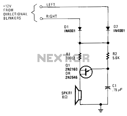
A unijunction transistor audio oscillator drives a small speaker. The oscillator's frequency is determined by resistor R2 and capacitor C2. The operating voltage is supplied from the car's turn-signal circuit(s) through D1 and D2. The diodes conduct current from...
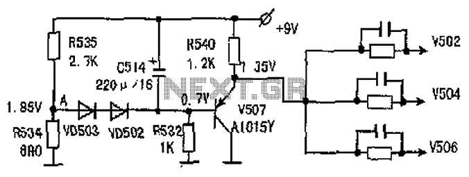
The common-emitter amplifier circuit V502, V504, V506 is designed to generate a static potential bias voltage through an emitter follower configuration, as illustrated in Figure 3. The active filter is formed by components V507, VD502, and VD503. The emitter...
This circuit demonstrates a dynamic AC signal level display drive, which can be utilized for audio level display purposes. The AC signal detection and drive control are achieved using the BA6124 integrated circuit, along with five external colored light-emitting...
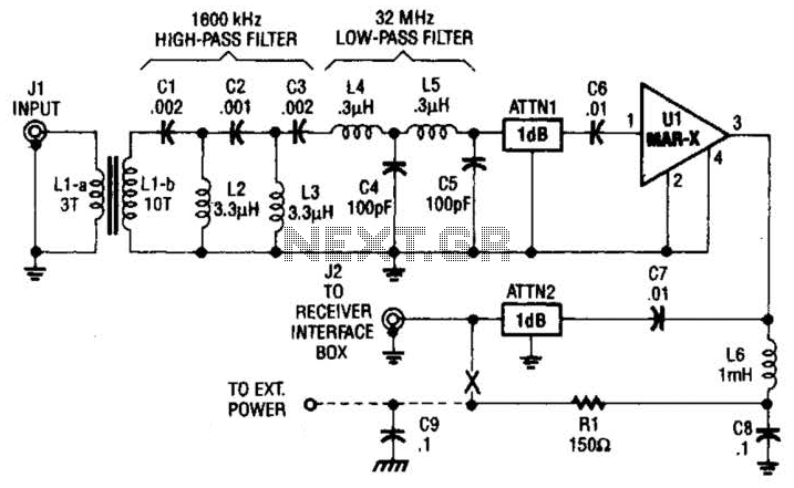
This high-frequency shortwave receiver preamplifier consists of a broadband toroidal transformer (LI-a and Ll-b), a complex LC network that includes a 1600 kHz high-pass filter and a 32 MHz low-pass filter, inductors L2 and L3 (26 turns of #26...
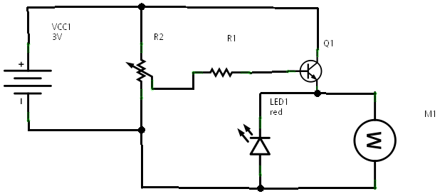
In a prior post titled "Timing is Everything," the application of PWM (Pulse Width Modulation) signals for controlling devices such as LEDs was discussed. This technique is particularly beneficial when working with digital devices, including microchips and microcontrollers, which...