
Amplifier power supply

The balanced dynamic microphone preamplifier described is designed to amplify low-level audio signals from dynamic microphones while maintaining a low noise floor and high fidelity. The circuit typically employs an operational amplifier (op-amp) configured in a differential mode to achieve a balanced input. This configuration helps to reject common-mode noise, making it ideal for use in environments with potential electromagnetic interference.
The input stage of the preamplifier consists of a transformer or a differential input circuit that connects to the microphone. The transformer serves to match the impedance of the microphone to the preamp, ensuring maximum power transfer and minimizing signal loss. The use of a transformer also provides galvanic isolation, which can further reduce noise and hum.
Following the input stage, the signal is processed by the op-amp, which amplifies the audio signal. The gain of the preamplifier can be adjusted using feedback resistors, allowing for flexibility in accommodating various microphone output levels. Capacitors may be employed to filter out unwanted high-frequency noise, ensuring that the amplified signal remains clean and clear.
The output stage of the preamplifier is designed to drive a load, such as a mixing console or audio interface, with a balanced output signal. This output can be configured as either a low-impedance or high-impedance signal, depending on the application requirements. Additional features such as phantom power can be included, allowing for the use of condenser microphones alongside dynamic types.
Overall, the design of this balanced dynamic microphone preamplifier emphasizes simplicity and effectiveness, making it a practical choice for audio professionals seeking reliable performance in various recording and live sound scenarios.This achievement shows that it is possible to create a balanced dynamic microphone preamp, it is relatively simple. This preamp is particularly suitable for microphones with an output impedance of 200 ohms to 600 ohms.
The advantage of the preamplifier. 🔗 External reference
Related Circuits
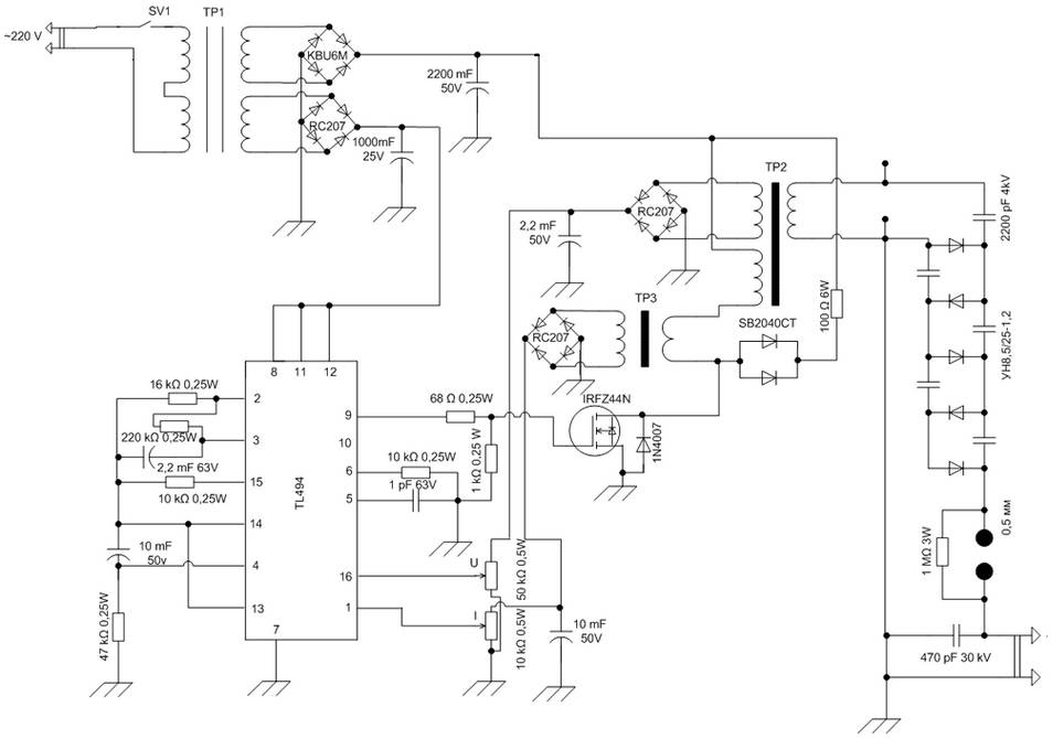
The schematic diagram is derived from the circuit of a High Voltage Power Supply utilizing the PWM IC TL494. This power supply requires a suitable alternating voltage source of 12 V / 800 mA. An alternating voltage is rectified...
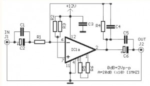
The video amplifier circuit utilizes the LM359 integrated circuit, which is a dual, high-speed, programmable current mode (Norton) amplifier. This circuit is suitable for general-purpose video amplification applications. The LM359 is designed to operate as a high-speed amplifier, making it...
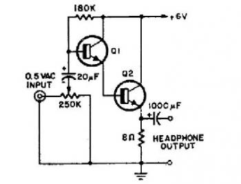
This schematic diagram illustrates a simple headphone amplifier circuit constructed using two NPN transistors. Suitable transistor options include the BC549C, as well as other NPN transistors such as the European equivalents BC548C, BC547C, BC239, 2N5818, or 2N2222. An audio...
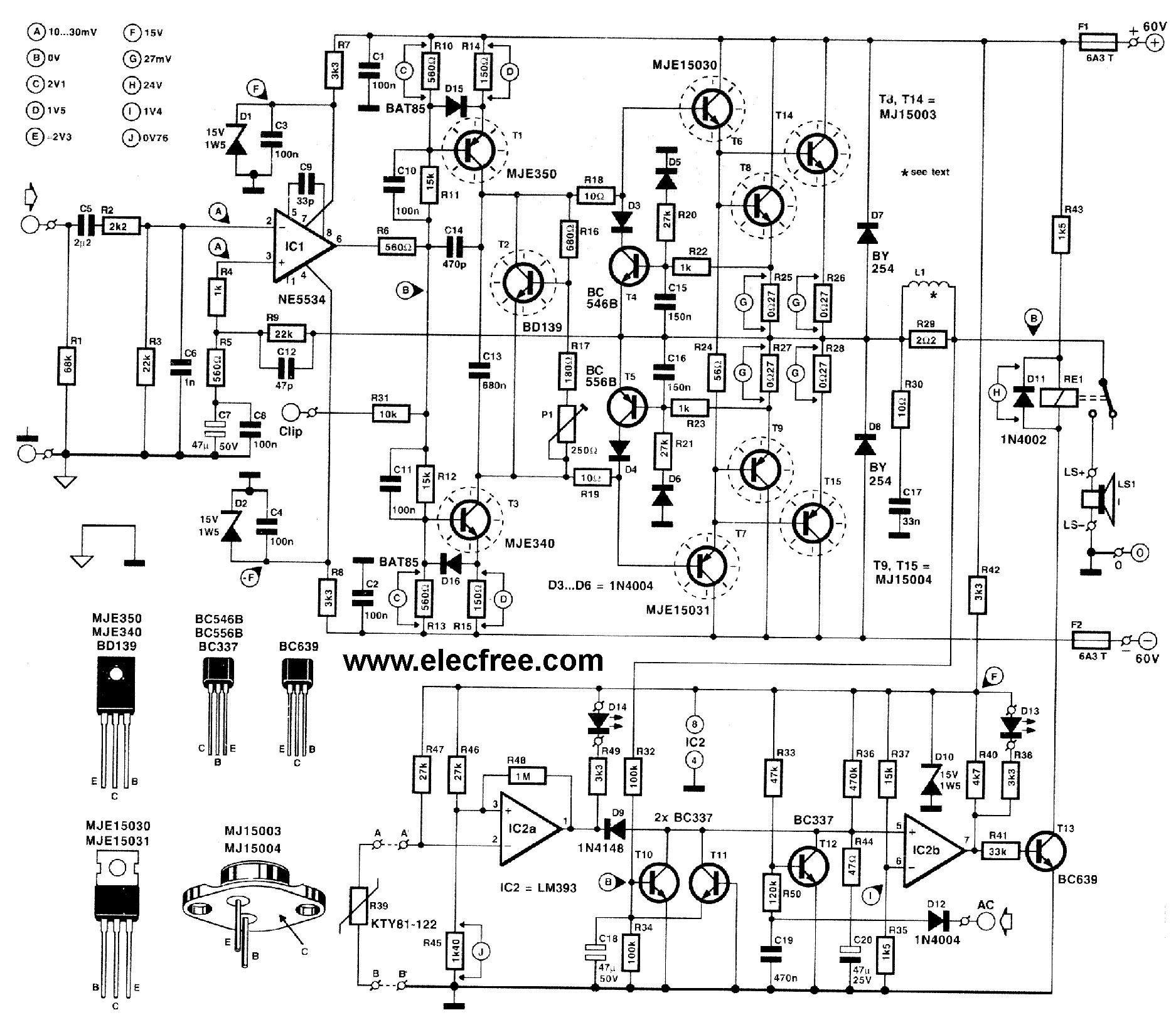
This circuit is designed for friends who are interested in high-power amplifier circuits. It can deliver approximately 300 Watts RMS and operates as an OCL (Output Capacitor-Less) Class AB amplifier, providing high sound power while systematically protecting the loudspeaker...
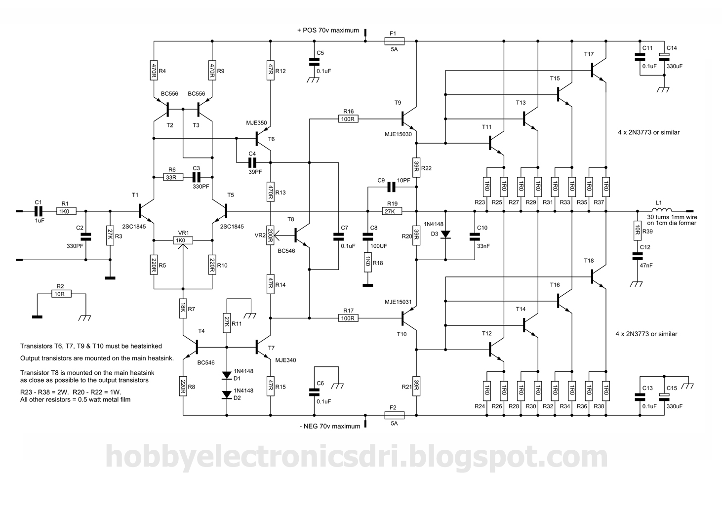
This amplifier was designed to utilize the otherwise unused TO3 power transistors that many hobbyists possess. With proper construction, the module can achieve high-quality performance and is rated for 300 watts into a 4-ohm load, depending on the power...
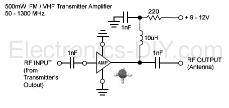
This is an aerial achievement low noise 500mW amplifier/booster designed for low power FM transmitters such as BA1404, BH1417, BH1415, and 433MHz transmitter modules. The amplifier utilizes a chip that incorporates various transistor stages and all necessary components within...