
High Voltage Power Supply scheme
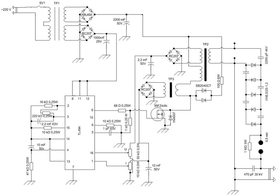
The High Voltage Power Supply schematic utilizing the TL494 PWM IC is designed for applications requiring stable high voltage outputs. The input section features a 12V AC source, which is rectified by a diode bridge to convert the AC voltage into DC. The diode bridge must be selected to handle a peak current of at least 1 A to ensure reliable operation. Following rectification, the output voltage can be adjusted through feedback mechanisms integrated into the TL494 control loop, allowing for fine-tuning of the output voltage to meet specific load requirements.
For the DC to DC converter section, the circuit effectively steps up the initial 5V input to a maximum of 30V. This conversion is achieved using a switching mechanism that rapidly toggles the input voltage, generating an alternating waveform that is then transformed into a higher voltage level. The hysteresis inverter, employing a Schmitt trigger, ensures stable oscillation and minimizes the risk of oscillation failure due to noise or minor voltage fluctuations.
The experimental results from the highly stable voltage source schematic demonstrate its robustness across various temperatures, highlighting its suitability for applications in environments with significant temperature variations. The design's ability to maintain a low temperature error is critical for precision applications where voltage stability is paramount.
The inverter circuit capable of generating voltages from 1.5V to 3V is particularly useful for low-power applications. By modifying a standard multivibrator circuit, the design achieves a frequency of approximately 130 kHz, facilitating efficient operation in small-scale electronic devices.
Finally, the precision high voltage regulator circuit based on the LM317L IC is designed for applications requiring a regulated output voltage. The circuit requires a minimum input voltage of 178V to function correctly and can deliver a regulated output voltage from 8V to 160V, making it versatile for various high voltage applications while maintaining a current output of 25 mA. The combination of these components creates a comprehensive power supply solution capable of meeting diverse electronic needs.The schematic diagram come from circuit: High Voltage Power Supply based PWM IC TL494 power supply. Go to that page to read the explanation about above power supply related circuit diagram. To supply the high voltage converter suitable source of alternating voltage 12 V / 800 mA. An alternating voltage is rectified by a diode bridge with an allowa ble current of 1 A. Converter output voltage is adjustable between 0. . This DC to DC Converter 5V to 30V schematic will convert 5 volt input voltage to 30V voltage. Direct current is converted into an alternating generator, which built on having the characteristic hysteresis inverter with Schmitt trigger and a resonant. Fig. 1 Highly stable source of voltage schematic Experimental studies of exemplary scheme of a highly stable source of voltage (Fig.
1) in the temperature range from -18 ° C to 50 ° C show that the temperature error of. A simple scheme to generate the inverter voltage from 1. 5V to 3V can be made on the basis of slightly modified the well-known multivibrator. Under these denominations in the scheme of the frequency converter is approximately 130 kHz. Inductance value. This is precision high voltage regulator circuit diagram based 3 terminal adjustable regulator LM317L IC. The circuit require input voltage Vin ‰¥ 178V and can provide output voltage ( V out) between 8 V to 160 V @ 25 mA.
We aim to transmit more information by carrying articles. Please send us an E-mail to wanghuali@hqew. net within 15 days if we are involved in the problems of article content, copyright or other problems. We will delete it soon. 🔗 External reference
Related Circuits
High voltage current sensing and monitoring can be designed using the LTC6101 operational amplifier. The current sensing circuit outlined is capable of measuring electrical current. The LTC6101 is a precision current sense amplifier designed to operate in high voltage environments,...
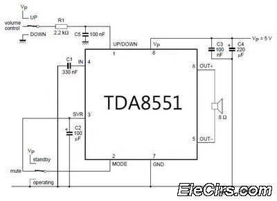
An amplifier with digital volume control can be designed predictably due to the simplicity of the circuit, which utilizes a single chip, the TDA8551. This series of mini amplifiers with digital volume control operates as a BTL (Bridge-Tied Load)...

This article was originally published in a slightly modified form in the QST magazine, December 1998 and January 1999, and in the Radio Amateur's Handbook, 1999. Visit the American Radio Relay League for information on these publications and a...
A switching power supply that has an output voltage significantly lower than its input voltage exhibits a unique characteristic: the current drawn from the supply is less than the output current. However, the input power (UI) is, naturally, greater...
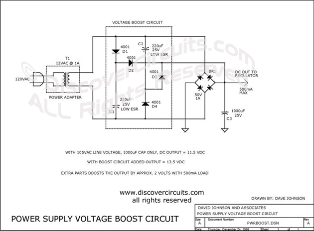
This circuit incorporates capacitors and diodes into a conventional transformer-based series regulator circuit to enhance its operational range. It ensures regulation under low line voltage conditions and can extract additional power from a standard plug-in power supply. The described circuit...
This circuit is designed as a warning flasher to alert road users to dangerous situations in low-light conditions. It can also function as a bicycle light, subject to applicable traffic regulations. White LEDs are recommended for use as a...