
High power transistor amplifier circuits
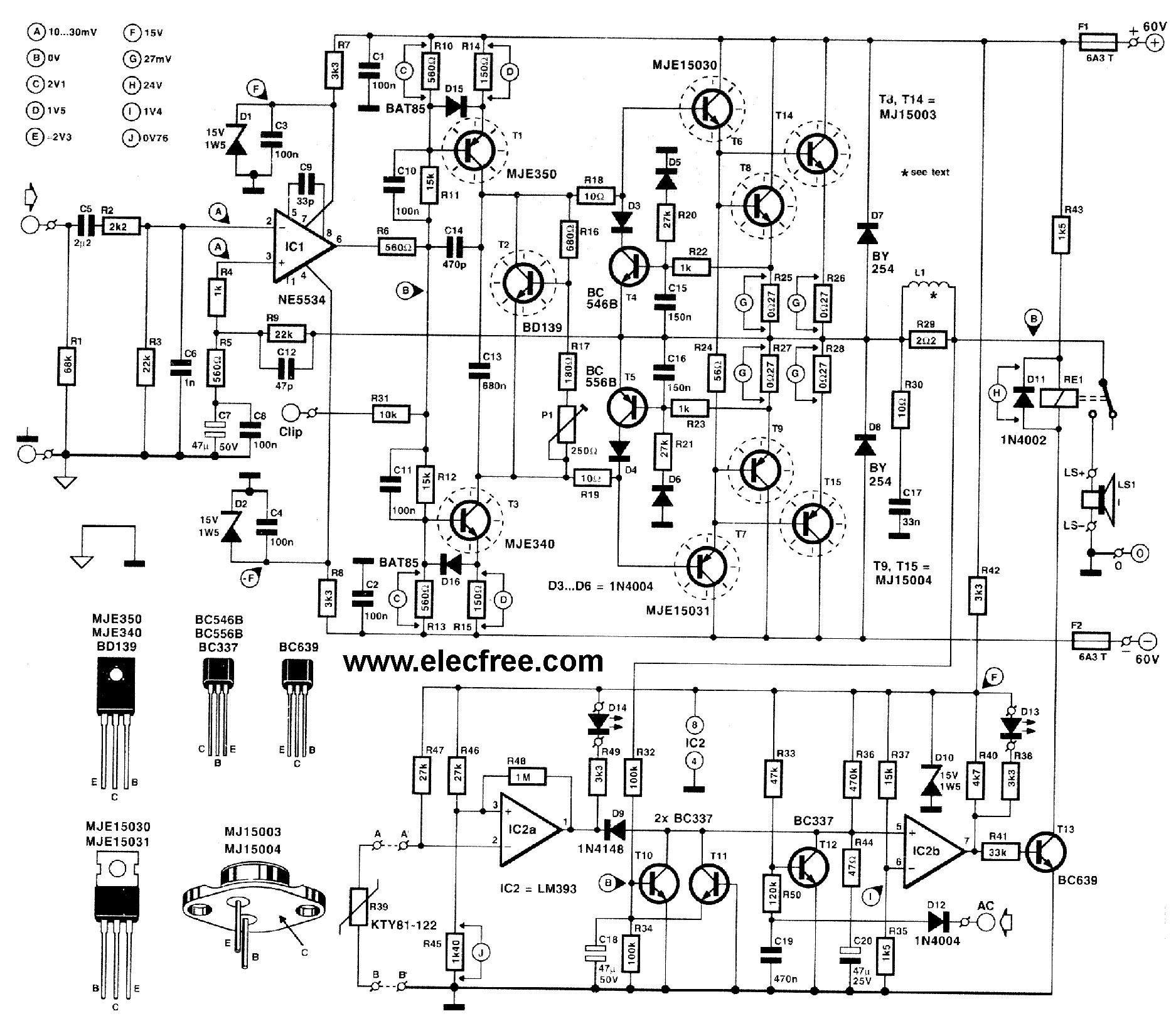
This high-power amplifier circuit is engineered to deliver robust audio performance, with a focus on both power output and speaker protection. The OCL configuration eliminates the need for output capacitors, resulting in improved sound quality by minimizing phase shift and distortion. The use of MJ15003 and MJ15004 transistors is critical, as they are known for their high current handling capabilities and thermal stability, making them suitable for high-power applications.
The circuit's design incorporates a feedback mechanism that enhances linearity and reduces harmonic distortion, which is essential for achieving high-fidelity sound reproduction. Additionally, the Class AB operation allows for a balance between efficiency and sound quality, ensuring that the amplifier can deliver substantial power without overheating.
For those interested in constructing this amplifier, it is important to note that the circuit may require careful assembly and fine-tuning of components to achieve optimal performance. The complexity of the circuit may pose challenges for beginners, as it involves multiple stages of amplification and requires precise component selection. Proper heat dissipation measures, such as heat sinks for the transistors, should also be implemented to prevent thermal runaway and ensure long-term reliability.
In summary, this high-power amplifier circuit is a sophisticated design suitable for car audio enthusiasts who seek to enhance their sound system. With its considerable power output and protective features, it is a valuable addition to any audio setup, provided that the builder has the requisite skills and knowledge to navigate its complexity.Follow the request of friends who likes High power Amplifier Circuit. I then beg for to advise this circuit. It has can to give the electric power about 300Watt RMS unless. Still be amp OCL Model Class AB give sound tall power and certainly should systematically protect that excellent a loudspeaker then torn difficult. Besides still use Transistor replace the integrated circuit then give waste matter feeling cancels bland three goes up and have MJ15003 and MJ15004 then have respond electric good enough power. When friends see the circuit has already, will have plentiful detail, then inappropriate for hobby Electronics man type.
But if friends want to try build, have no a problem, be lucky. Today we try to come to see the idea power Amplifier for Car. I sees this circuit, designed come to well. There is tall drive arrives at 200W is the character Amp OCL very be Class AB amplifier make good moderately sound. Besides still systematically protect excellent loudspeaker. But I thinks this circuit may inappropriate with a novice. Because of use many equipments, circuit absorb overlap, must fine decorate thoroughly. But friends at like sound good quality As a result be worthwhile very. See be circumspect in power Amplifier for car circuit get yes. 🔗 External reference
Related Circuits
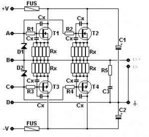
Amplifier circuit featuring a MOSFET output stage, serving as an alternative to the output stage that utilizes bipolar transistors. Advantages of the MOSFET amplifier include ease of operation, the ability to handle hundreds of watts with straightforward parallel configurations,...

The inverting input is maintained at a low level via a 10K resistor when the circuit is powered on but not in use. During measurement activities, including calibration measurements where the input is floating, this resistor is disconnected. The...
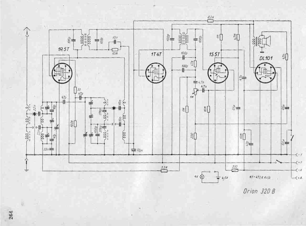
Create a repository of circuits and service data for vintage valve and transistor radios. While many resources are available online, they often come at a cost. The intention is to share circuits and manuals with others rather than profit...
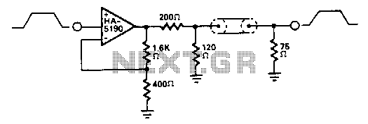
The HA-5190 can drive the 75-ohm coaxial cable with signals up to 2.5 V peak-to-peak without the need for current boosting. In this circuit, the overall gain is approximately unity due to the impedance matching network. The HA-5190 is a...
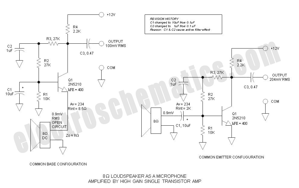
Single Transistor Amplifier Revisited Part 3, Common Base vs Common Emitter Configuration, Update One nagging question that I have long had is this: How do... The single transistor amplifier is a fundamental building block in electronic circuits, and its configurations—common...
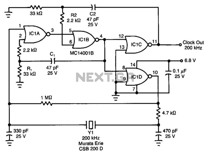
Ceramic resonators are suitable for low-power, low-frequency clock sources, despite their 30-ppm temperature coefficient. However, they exhibit troublesome spurious-resonance modes. This circuit effectively rejects all but the fundamental mode of the resonator. The clock circuit operates within a temperature...