
Amplifier Timer
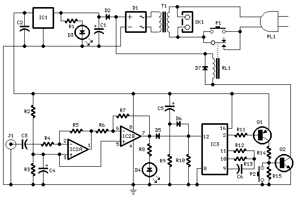
This circuit is designed to manage the operational state of an amplifier or similar device based on the presence of an audio signal. The core components include operational amplifiers, a timer IC, transistors, and a relay, which work together to achieve the desired functionality.
The circuit begins with an audio input, which is processed by operational amplifiers IC2A and IC2B. These components amplify the low-level audio signal and convert it into a square wave, facilitating easier detection of the signal's presence. The output of the second operational amplifier feeds into an LED indicator (D4), which visually indicates the presence of the audio signal.
The timer IC (IC3) plays a crucial role in monitoring the duration of the audio signal's absence. Initially, when an audio signal is detected, D4 illuminates, which resets the timer, preventing it from counting down. The timer's output at pin 2 remains low, which keeps the connected transistors in an "on" state, allowing current to flow through the relay. This operation ensures that the connected appliance, via connector SK1, remains powered.
If the audio signal is absent for 15 minutes, the timer completes its countdown, and pin 2 transitions to a high state. This change turns off the transistors, deactivating the relay and consequently cutting power to the appliance.
The circuit is equipped with a manual override switch (P1), allowing the user to turn on the device regardless of the audio signal state. This feature provides flexibility for scenarios where immediate operation is required without waiting for the audio signal to be detected.
Overall, this circuit effectively manages power consumption by turning off devices during periods of inactivity, thus contributing to energy efficiency. The use of visual indicators and manual controls enhances user interaction and operational reliability.This circuit turns-off an amplifier or any other device when a low level audio signal fed to its input is absent for 15 minutes at least. Pushing P1 the device is switched-on feeding any appliance connected to SK1. Input audio signal is boosted and squared by IC2A & IC2B and monitored by LED D4. When D4 illuminates, albeit for a very short peak, IC3 is reset and restarts its counting. Pin 2 of IC3 remains in the low state, the two transistors are on and the relay operates. When, after a 15 minutes delay, no signal appeared at the input, IC3 ends its counting and pin 2 goes high.
🔗 External reference
Related Circuits
The gain of the low-cost integrated circuit (IC) is internally fixed at no less than 34 dB (50 times). A unique input stage allows input signals to be referenced to ground. The output is automatically self-centering to one-half the...
Enthusiasts understand that connecting headphones directly into the universal headphone jack to listen to VCD results in subpar sound quality. The audio performance when using a tape player is similarly affected. An amplifier is necessary, and the RC4558, which...
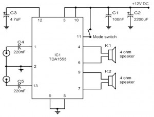
The provided schematic represents a car stereo amplifier circuit that can be utilized in cars or other vehicles. The circuit is based on the TDA1553, which is a Class-B audio amplifier. This circuit is straightforward, consisting solely of the...
This microphone preamplifier utilizes the low-noise integrated circuit uA739. The circuit serves as an example of an effective preamplifier design for dynamic microphones. The integrated circuit contains two identical preamplifier circuits, with the second preamp functioning in the same...
This scan is from an old ETI Circuits #2 publication from the 1970s. It contains valuable operational amplifier information that is highly useful. With some knowledge, the six circuits presented serve as an instant reference, enabling various applications. These...
4 Stage FM Transmitter. This FM transmitter circuit utilizes four radio frequency stages, functioning as a VHF oscillator. It is available for wholesale through fmuser, including the CZE and CZH models of FM transmitters, which are suitable for OEM...