
standard operational amplifier op amp circuits
The ETI Circuits #2 publication features a series of six operational amplifier circuits designed for various applications. These circuits are essential for anyone seeking to understand the fundamentals of op-amps and their practical uses in electronic design. The circuits are categorized based on their functionality, including amplifiers, filters, and signal processing applications, each demonstrating the versatility of operational amplifiers.
1. **Inverting Amplifier**: This circuit configuration allows for signal inversion and amplification, with the gain determined by the ratio of two resistors. It is fundamental for audio signal processing and can be used to create various effects.
2. **Non-Inverting Amplifier**: Opposite to the inverting amplifier, this configuration provides an output that is in phase with the input signal while also offering gain. This is particularly useful in applications requiring signal buffering.
3. **Summing Amplifier**: This circuit can combine multiple input signals into a single output, making it ideal for mixing audio signals or combining sensor outputs in data acquisition systems.
4. **Differential Amplifier**: This configuration amplifies the difference between two input signals while rejecting any common-mode noise. It is crucial in applications requiring precise measurements, such as instrumentation.
5. **Integrator Circuit**: This circuit produces an output that is proportional to the integral of the input signal over time. It is commonly used in analog computing and signal processing applications.
6. **Differentiator Circuit**: This configuration generates an output that is proportional to the rate of change of the input signal, making it useful for edge detection in signal processing.
Each circuit is designed to be straightforward, allowing users to easily replicate and modify them for their specific needs. The publication serves as an excellent resource for both beginners and experienced engineers, providing insights into analog design principles and practical applications. The rich content encourages experimentation and adaptation, fostering a deeper understanding of electronic circuit design, particularly in achieving high-quality analog sound.This scan is from my old ETI Circuits #2 from the 70 ²s. It`s about the best op-amp info you are likely to find. With a bit of knowledge, these six circuits are an instant ready-reckoner and allow you to do almost anything! If you want to learn then they are ideal to have sat next to a larger circuit to help with the comprehension process.
Like y our mixer project! BTW, how`s it going with that Because of some recent site activity, I`ve checked and realised a picture was missing from a previous post here: so I`ve updated that and added a bit of info from the same mag above. There`s shedloads in it. I can see why I never chucked it out now! I`ve found someone here in Australia with the same disposition as me check the circuits! Nice and simple, and you`ll get that authentic analogue sound, as well as getting some understanding along the way.
Most of this sort of information I vigorously used and modified (along with other stuff, of course), to make our Crawling Chaos hardware. So it does work! :-D 🔗 External reference
Related Circuits

Below 10 MHz, the development of engineering models is relatively straightforward and not significantly influenced by printed circuit board layout. In the VHF range, parasitic circuit elements and unwanted coupling can severely impact efforts to achieve cost-effective performance without...
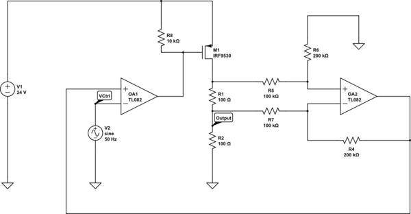
Create a 0-25 mA current limiter using a control voltage input of 0-5 V to regulate the current through a resistive load (R2), which can vary between 0-200 ohms. The O2 operational amplifier (op-amp) functions as a differential amplifier...
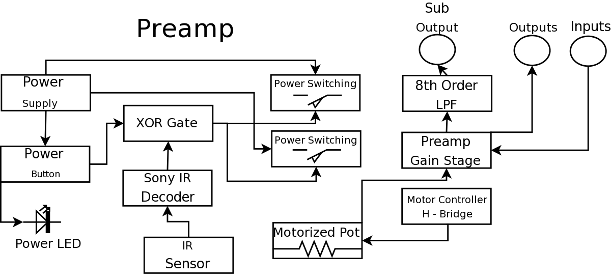
During a Digital Projects Lab, the professor suggested incorporating more circuit-level work into a project. To achieve this, a preamplifier was designed, which included an infrared (IR) remote control to replace a previously built version. The earlier preamplifier functioned...
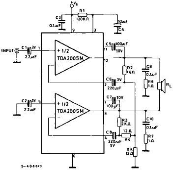
The TDA2005 is a Class B dual audio power amplifier package specifically designed for car radio applications. It facilitates the easy design of car radio power boosters. The TDA2005 power amplifier is engineered to deliver high-quality audio output in automotive...
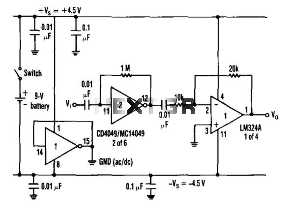
When an inverter is biased with a resistor from its input to output in the range of 100 kΩ to 10 kΩ and is capacitor coupled, it exhibits amplifier characteristics. Furthermore, when a split power-supply bus is needed and...
This page is provided to the domain owner free of charge by Sedo's Domain Parking. The domain owner and Sedo do not have any relationship with third-party advertisers. References to any specific service or trademark are not controlled by...