
Dynamic Mic Preamplifier Circuit
This microphone preamplifier circuit is designed to provide high-quality audio signal amplification for dynamic microphones. The uA739 is a dual operational amplifier that ensures low noise levels and high fidelity in audio applications. The circuit layout typically includes a power supply connection, where the voltage divider formed by R1 and R4 sets the appropriate biasing for the non-inverting inputs of both preamps. This biasing is crucial for maintaining the linearity and performance of the preamp, especially under varying input signal conditions.
The RC filter comprising R3 and C4 serves to attenuate any unwanted high-frequency signals that may be picked up by the microphone, ensuring that only the desired audio frequencies are amplified. This filtering is essential for maintaining audio clarity and preventing distortion from high-frequency noise. The inclusion of the R7/C6 frequency compensation network is vital for stabilizing the gain of the amplifier at higher frequencies, thereby preventing unwanted oscillations that could compromise audio quality.
The input impedance of 47 kΩ is particularly advantageous, as it allows for a wide range of dynamic microphones to be connected without significant loading effects, thus preserving the microphone's performance characteristics. The output impedance, measured in several hundred ohms, is suitable for interfacing with standard audio equipment, such as mixers or audio interfaces.
The frequency response of the preamp, extending from 20 Hz to 20 kHz, ensures that it captures the full range of audible frequencies, making it suitable for various audio applications, from music recording to broadcasting. The ability to remove the low-pass filter and achieve an upper cutoff frequency of 80 kHz provides additional flexibility for specialized applications that may require broader frequency handling.
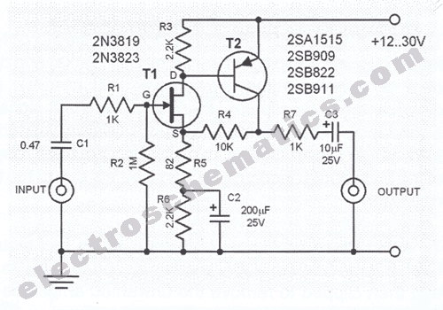
In summary, this microphone preamplifier circuit exemplifies a robust and versatile design, capable of delivering high-quality audio amplification for dynamic microphones while maintaining low noise and high fidelity. The option to replace the uA739 with other compatible integrated circuits, such as the TBA231 or SN76131, further enhances the circuit's adaptability for different design requirements.This mic preamp uses the low noise IC uA739. The circuit is an example of how a good preamplifier can be designed for dynamic microphones. The IC houses two identical integrated preamp circuits. The second preamp is used in identical manner for the second channel of the stereo microphone. The non-inverting input is biased at about 50% of the power supply. This bias voltage is set by the voltage divider circuit R1 and R4. The point between R1 and R4 is used commonly for both channels. The unwanted HF signals coming from the microphone are filtered out by the RC-circuit composed of R3/C4. Frequency compensation is done by the R7/C6 circuit. The values of R7 and C6 were designed to avoid oscillation at the amplification level of 100. The input impedance is about 47K. This means that a normal dynamic microphone gets connected to a high impedance preamp which in turn produces good results.
The output impedance is about several hundred ohms. THe maximum peak-peak output voltage is about several volts lower than the supplied power. The frequency range is from 20Hz to 20KHz (-3dB). The upper cutoff frequency is 80KHz when the low-pass filter is removed from the circuit. The IC shown can be replaced with TBA231 or SN76131 without changind the external circuit. 🔗 External reference
Related Circuits
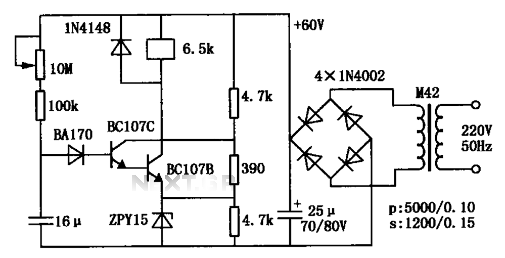
The circuit is a relay delay pull transistor configuration. Initially, when powered, the 16 µF capacitor has a voltage of zero, resulting in both transistors being off, and the relay remains inactive. As the 16 µF capacitor charges over...
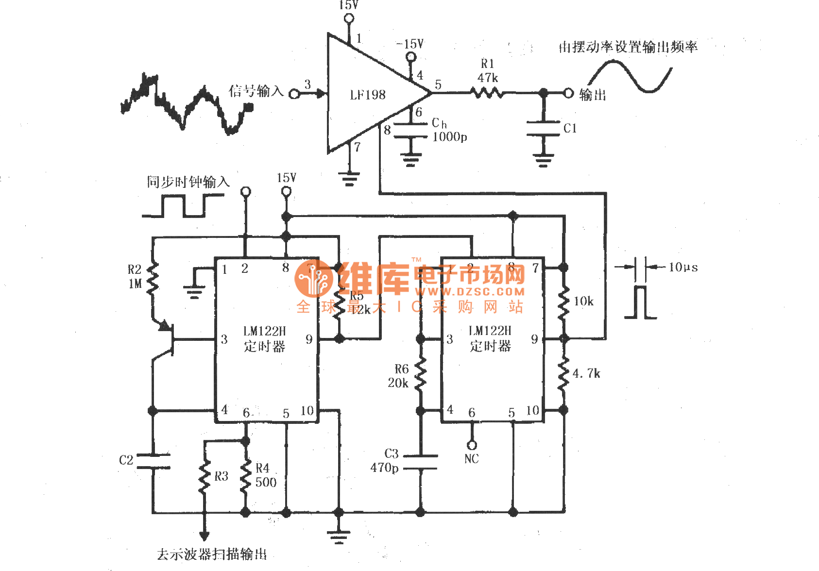
A synchronous clock signal is fed into a cascade of timer circuits composed of two LM122H devices. The synchronization clock is then converted into a pulse of the desired width, which is added to the LF198 logic end (pin...
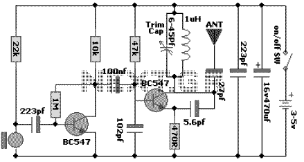
The following schematic diagram shows the design of a 100 MHz Radio Frequency RF Oscillator Circuit. The electrets microphone picks up and amplifies sound then fed it into the audio amplifier stage built around the first transistor. The output...
This LED table or reading lamp circuit can be utilized for various applications, such as a reading lamp for a bed, a desktop or table lamp, a keyboard lamp (to illuminate the keys of a computer keyboard in low...
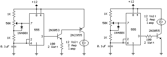
The schematic diagram illustrates a 12 Volt Car Lamp Dimmer Circuit Design utilizing a 555 Timer. This circuit can be employed to dim a standard 25-watt lamp. The 12 Volt Car Lamp Dimmer Circuit utilizes a 555 Timer in astable...
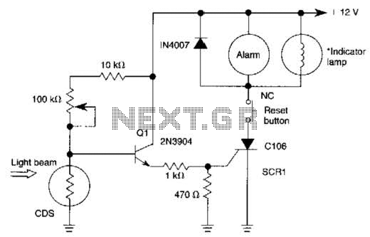
When the light beam that falls on the CDS photocell is interrupted, the transistor (EN3904) conducts, triggering SCR1 (CI06) and activating the alarm bell. SI resets the SCR. The alarm bell should be a self-interrupting electromechanical type. The lamp...