
LM56 diagram of Circuit of the Thermostat project
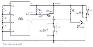
The LM56 thermostat circuit is designed to regulate temperature by utilizing the IC's dual-output functionality. The circuit operates by monitoring the temperature through its internal sensor, which provides a reference for the temperature thresholds VT1 and VT2. The resistors R1, R2, and R3 are critical in setting these thresholds, as they form a voltage divider that allows for precise control over the trip points. The output behavior of the IC is defined by the temperature conditions: when the ambient temperature rises above the set point T1, output 1 transitions to a low state, indicating that cooling is required. Conversely, when the temperature drops below the set point, output 1 returns to a high state, signaling that the heating or cooling mechanism can be turned off.
The internal architecture of the LM56 includes two voltage comparators that compare the voltage from the internal temperature sensor against the reference voltage set by the resistors. This allows for accurate detection of temperature changes and ensures reliable operation. The hysteresis feature is essential for preventing rapid cycling of the outputs, which can occur if the temperature hovers around the set point. By implementing hysteresis, the circuit can maintain stable operation without unnecessary switching, thus enhancing the longevity of connected components.
Overall, the LM56 thermostat project circuit is a practical solution for temperature control applications, offering simplicity in design while incorporating essential features for effective performance. The use of external resistors allows for customization of the temperature set points, making it adaptable to various requirements.The values of LM56 Thermostat project Circuit diagram of R1, R2 and R3 for the points of travel, VT1 and VT2 can be determined using the subsequent equations. This thermostat of electronic circuit with IC LM56 diagram what simple project, you can use as reference.
As you know, IC LM56 is correct double output thermostat low power characterized by National Semiconductors. trip temperature stable 2 points called VT1 and VT2 are made with dividing the LM56 IC 1, 250 reference internal voltage volts by three outside resistors (R1, R2 and R3) component. There are 2 digital outputs for LM56 IC which is that output1 becomes weak when the temperature increases over T1 and goes high when the temperature decreases below (temperature T1 ±Hysteresis).
Component IC LM56 has a variety of useful features as internal voltage reference internal temperature sensor, 2 internal voltage comparators, etc. 🔗 External reference
Related Circuits

Magnetic stripe reader, electric circuit theory, logic operation. The wiring diagram does not connect the transistor in the circuit. The collector pin of the transistor connects to the tip pin of the jack. The base pin of the transistor...

The following circuit illustrates the electrical circuit diagrams for the Toyota Supra. The diagrams indicate the point at which the power source is received. The electrical circuit diagrams for the Toyota Supra provide a comprehensive overview of the vehicle's electrical...

AN7415 based FM stereo demodulator circuit. 1.6 to 7V operating voltage range. High gain and low distortion. The AN7415 is a versatile integrated circuit designed for FM stereo demodulation applications. This circuit operates within a voltage range of 1.6 to...
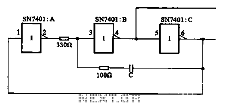
The clock signal generating circuit utilizes an RC configuration, commonly applicable in most TTL systems. This circuit requires a set of six inverters, specifically three inverters from the SN7401 series. The clock frequency is determined by the values of...

The circuit illustrated in the figure is a dimmer using the 555 timer as the core component. The 555 timer, along with resistors R1, RP, R2, and capacitor C1, forms an astable multivibrator. The oscillation frequency, f, is calculated...
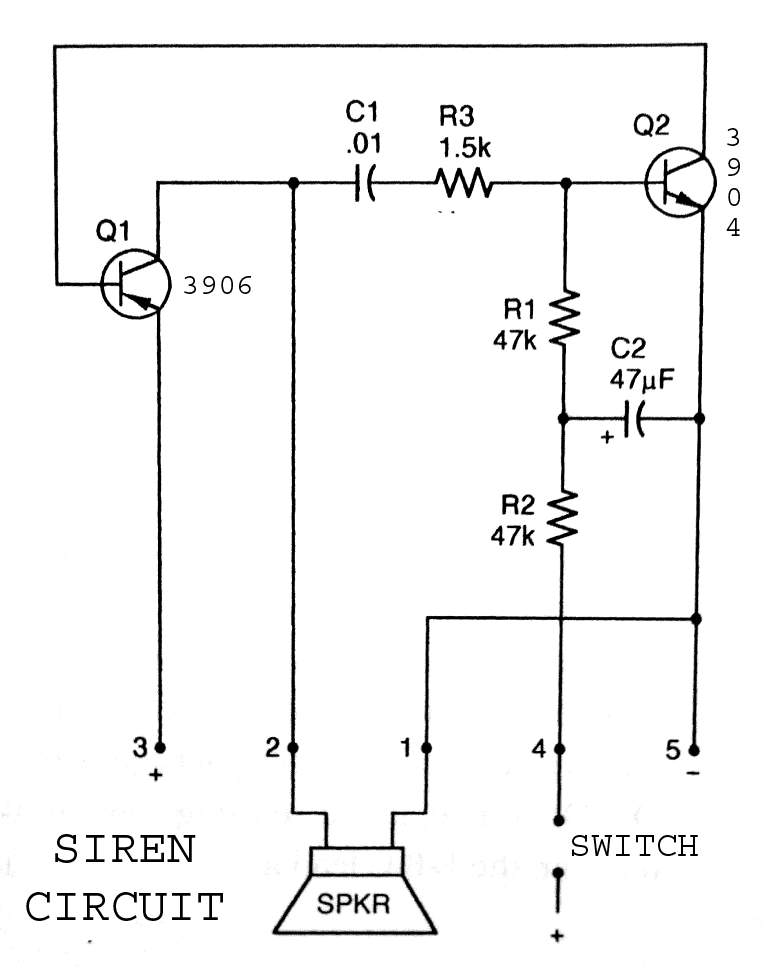
3904 3906 Siren Circuit. The circuit generates a wailing siren sound when the switch is activated. The 3904 3906 Siren Circuit is designed to produce a distinctive wailing sound, commonly used in alarm systems and signaling devices. The circuit utilizes...