
Battery discharge status indicator circuit
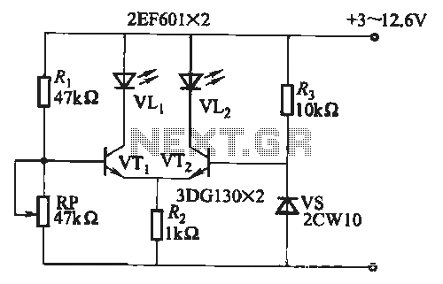
The circuit described utilizes light-emitting diodes (LEDs) to provide visual indicators of battery voltage levels. The primary components include three LEDs: VLi, L2, and VLz, each serving a specific function based on the voltage detected from the battery.
The operational range of the circuit is defined by the battery voltage, which is monitored through a voltage divider network connected to a microcontroller or a comparator. When the battery voltage is within the specified range of 7 to 12.6V, VLi is powered and remains illuminated at a steady brightness, indicating that the battery is functioning normally.
As the voltage decreases and falls below 7V, VLi transitions to a red state, indicating a warning condition. Concurrently, L2's brightness diminishes, which serves as a secondary indicator of the declining battery condition. This dual LED indication allows for immediate visual feedback regarding the battery's status.
When the voltage further declines to between 2.5V and 6V, VLz is activated, providing a critical warning that the battery voltage is dangerously low. This stage signals that immediate action is required, either by recharging the battery or replacing it entirely.
To ensure accurate voltage monitoring and LED functionality, the circuit incorporates resistors to limit current through the LEDs and a voltage regulator to maintain consistent operation across varying input voltages. The values of these resistors can be adjusted based on the specific requirements of the application, allowing for flexibility in monitoring different battery types and voltages.
This design is suitable for applications where battery monitoring is essential, such as in portable devices, electric vehicles, or renewable energy systems, providing a reliable method to ensure that battery levels remain within safe operational limits.When the battery voltage is 7 ~ 12. 6V range, the light emitting diode VLi lights, which light cutting almost unchanged. If the battery voltage falls under 7V VLi beginning red light emitting diode, and a light emitting diode , L2 brightness decreases. When the two are the same brightness light-emitting diode, the battery should be recharged or replaced. When the battery voltage when Yap in 2. 5 ~ 6V range, VLz red, battery voltage has forecast below normal. Select the appropriate indicator of the resistors and the regulator, can adapt to the needs of different monitoring battery voltage.
Related Circuits

A static device that couples two circuits to transfer alternating current (AC) from one circuit to another through electromagnetic induction. The current maintains the same frequency but may vary in voltage, phase, or impedance values. A transformer consists of...
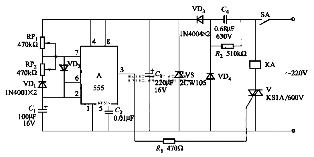
An automatic cycle switch circuit utilizing a 555 integrated circuit (IC) as the control element. It incorporates a capacitive step-down circuit and employs a bidirectional thyristor to control relays or loads with specific on and off timing. The circuit...
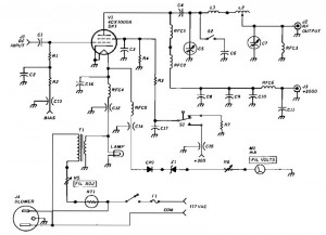
1500 Watt RF Amplifier circuit can be utilized to drive a transmitter antenna. It is also applicable for powering RF high power sources, microwave heating, and other uses. The 1500 Watt RF Amplifier circuit is designed to amplify radio frequency signals,...
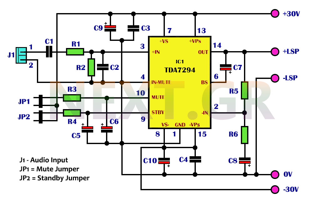
The integrated TDA7294 from SGS Thomson is a high-frequency acoustic power amplifier that boasts true high-precision specifications, making it suitable for various applications. Its standout feature is the significantly higher output power compared to typical amplifiers with similar distortion...
There is no substitute for sheer power—low-efficiency speakers, outdoor sound systems, or perhaps the full dynamic range of a high-power amplifier. Whatever the requirement, this super power module should meet the needs. The amplifier can be divided into three...
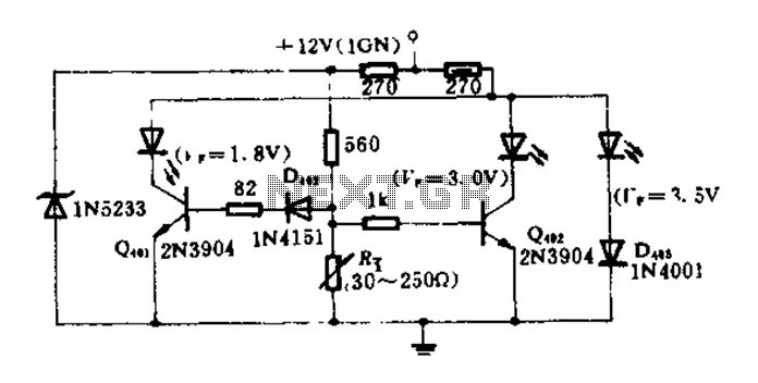
The circuit diagram illustrates how an oil pressure sensor is transformed into a variable resistor, denoted as Rt. Variations in Rt lead to changes in the biasing of each transistor, which in turn controls three LEDs (red, yellow, and...
Warning: include(partials/cookie-banner.php): Failed to open stream: Permission denied in /var/www/html/nextgr/view-circuit.php on line 713
Warning: include(): Failed opening 'partials/cookie-banner.php' for inclusion (include_path='.:/usr/share/php') in /var/www/html/nextgr/view-circuit.php on line 713