
Amplitude Modulator with OTA
This circuit is designed for high-efficiency amplitude modulation, capable of achieving a modulation depth of 99%. The operational frequency range extends up to 200 kHz, making it suitable for various applications in communication systems. The circuit typically comprises several key components, including transistors for amplification, resistors for biasing, and capacitors for filtering and coupling signals.
The modulation process begins with an input signal, which is fed into the circuit. The transistors used in the design function as amplifiers, boosting the input signal's amplitude while maintaining the fidelity of the modulation. The circuit configuration may include feedback mechanisms to stabilize the gain and improve linearity, ensuring that the output signal closely follows the input signal's variations.
Furthermore, the circuit may incorporate a low-pass filter to eliminate unwanted high-frequency components that could affect the quality of the modulation. This filter is essential in maintaining the integrity of the modulated signal and preventing distortion in the output.
To achieve the desired modulation depth, careful selection of component values is crucial. Resistors and capacitors must be chosen to match the specific frequency response required for optimal performance. Additionally, the power supply must provide sufficient voltage and current to support the amplification stages without introducing noise or fluctuations in the output.
Overall, this circuit represents a robust solution for achieving high levels of modulation at significant frequencies, making it applicable in various electronic communication devices and systems.Circuit described in the schematic diagram below can achieve 99% modulation easily with maximum frequency of 200kHz. The amplification of this circuit can be.. 🔗 External reference
Related Circuits
This rotary speed regulator circuit schematic enables control over the rotational speed of a borer or drilling machine. This project is based on the principle that... The rotary speed regulator circuit is designed to modulate the speed of electric motors...
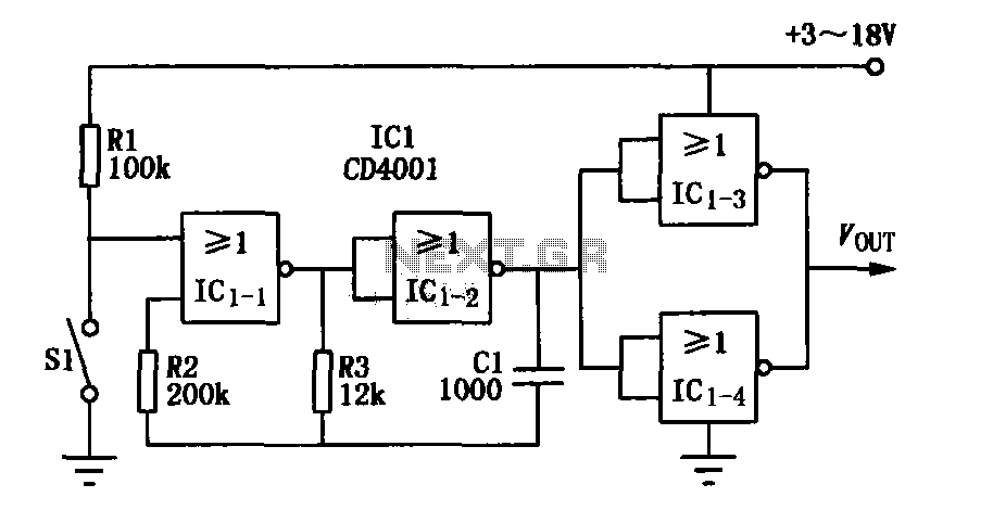
The core elements of this circuit are the second four-input NOR gate terminal IC CD4001. The entire circuit features a simple structure, with fewer components, making it easy to construct, particularly for remote control transmitters or carrier modulation transmission....
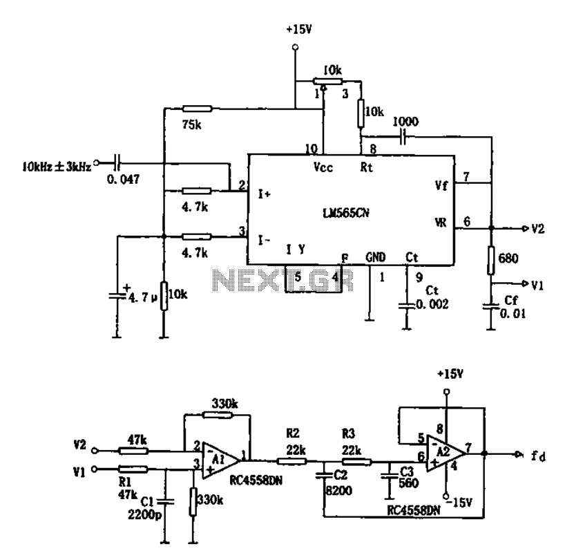
The circuit utilizes a 10 kHz and 3 kHz LM565CN to create an FM demodulation setup. The output diagram (b) illustrates the differential demodulation outputs V1 and V2 from the differential amplifier A1, which provides level displacement and amplification....
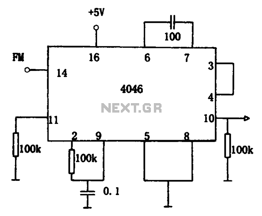
The circuit utilizes the 4046 Phase-Locked Loop (PLL) for FM demodulation, incorporating an intermediate frequency (IF) FM demodulation output based on the input signal frequency. The 4046 PLL is a versatile integrated circuit that can be configured for various applications,...
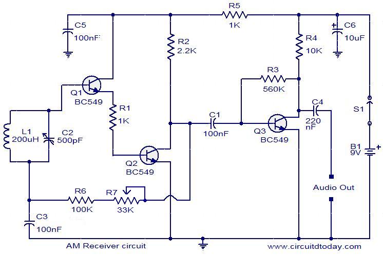
Circuit diagram of a modulator circuit in a transmitter and receiver of amplitude modulation. The modulator circuit in an amplitude modulation (AM) transmitter and receiver plays a crucial role in the process of encoding information onto a carrier wave. In...
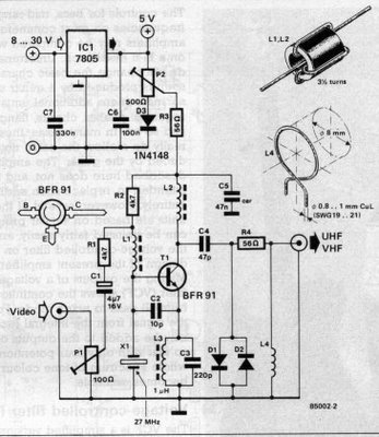
The electronic circuit is a TV modulator, which functions primarily as a transmitter. It is a compact transmitter that operates as a simple oscillator generating frequencies within the VHF or UHF range. The oscillator is modulated with a video...