
Circuit diagram of a modulator circuit in a transmitter and receiver of a amplitude modulation
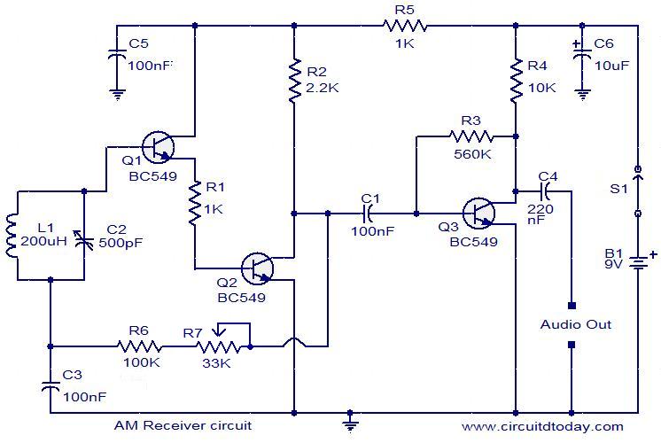
The modulator circuit in an amplitude modulation (AM) transmitter and receiver plays a crucial role in the process of encoding information onto a carrier wave. In a typical AM system, the modulator combines the audio signal (the baseband signal) with a high-frequency carrier wave. This process results in a modulated signal that can be transmitted over long distances.
The basic components of an AM modulator circuit include a carrier oscillator, which generates a high-frequency sine wave, and a mixer or modulator stage, where the audio signal is combined with the carrier wave. The output of the modulator is an amplitude-modulated signal, where the amplitude of the carrier wave varies in accordance with the instantaneous amplitude of the audio signal.
In a transmitter, the modulated signal is then amplified using a power amplifier before being transmitted through an antenna. The antenna radiates the modulated carrier wave into the atmosphere, allowing it to travel to the receiver.
On the receiving end, the process is reversed. The receiver captures the transmitted signal using its antenna, and the incoming signal is fed into a demodulator circuit. The demodulator extracts the original audio signal from the modulated carrier wave. This is typically done using a diode detector or a synchronous demodulator, which retrieves the audio signal by rectifying the modulated signal and filtering out the carrier frequency.
The circuit diagram of the modulator typically includes the following elements:
1. **Carrier Oscillator**: Generates the high-frequency carrier wave.
2. **Audio Input Stage**: Accepts the audio signal to be transmitted.
3. **Mixer/Modulator**: Combines the audio signal with the carrier wave.
4. **Output Stage**: Provides the modulated signal to the power amplifier.
5. **Power Amplifier**: Boosts the modulated signal for transmission.
6. **Antenna**: Radiates the modulated signal into the environment.
In summary, the modulator circuit is essential for transforming the audio information into a form suitable for wireless transmission, enabling effective communication over radio frequencies.circuit diagram of a modulator circuit in a transmitter and receiver of a amplitude modulation. 🔗 External reference
Related Circuits
The circuit depicted in the figure is a 567 FM demodulation circuit. The FM signal enters through pin 3, and the demodulated output signal is available at pin 5. The center frequency of the FM signal that the circuit...
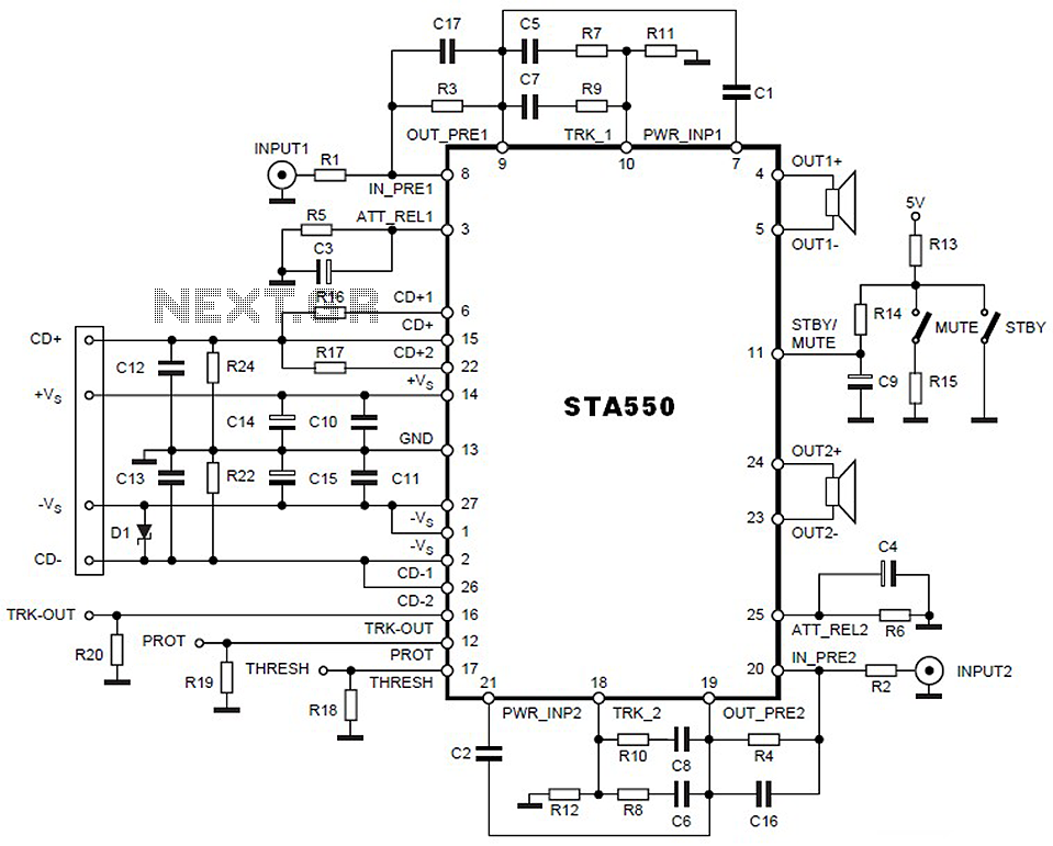
This is a 2 x 70W audio power amplifier circuit built using a single IC STA550. The amplifier circuit requires a few external components, primarily resistors and capacitors, and is straightforward to design. The STA550 audio amplifier can provide...
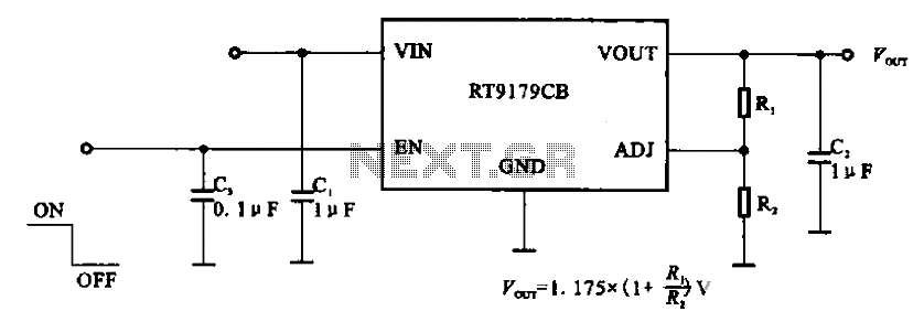
The RT9179CB is a power management chip utilized in power supply circuits. It serves as a linear regulator power management chip. This circuit is commonly employed in various products, such as computer motherboards, LCD monitors, and others. It is...
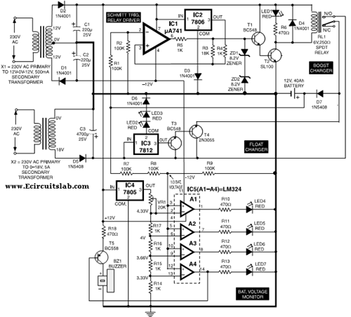
This circuit illustrates the use of the 7806 IC in an automatic battery charger circuit diagram. It is designed for a car battery with an approximate rating of 40 Ah. The automatic battery charger circuit utilizing the 7806 integrated circuit...
The buba oscillator initially failed to oscillate. The first step is to check the fundamental components, as minor errors in the values of capacitors, resistors, and inductors can significantly impact performance. It is advisable to measure component values with...
This simple circuit is based on the well-known integrated circuit LM3915. The main characteristic of this integrated circuit is its ability to manage 10 Light Emitting Diodes (LEDs) in a logarithmic scale, with a 3dB difference between the LEDs,...