
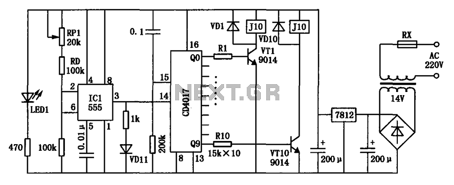
Rotative Speed Regulator Borer Driller Controller
The rotary speed regulator circuit is designed to modulate the speed of electric motors commonly used in drilling and boring applications. The key components typically include a variable resistor, a transistor, and a microcontroller or a dedicated speed control IC, which collectively manage the voltage and current supplied to the motor.
In this circuit, the variable resistor allows the user to adjust the resistance, which in turn alters the voltage drop across the motor. This adjustment leads to a change in the speed of the motor's rotation. The transistor acts as a switch that can handle high current loads while being controlled by a low voltage signal from the microcontroller or speed control IC.
The microcontroller can be programmed to provide precise control over the motor speed, enabling features such as ramp-up and ramp-down speeds to prevent mechanical stress during operation. Feedback mechanisms, such as tachometers or encoders, may be integrated into the circuit to provide real-time speed monitoring and adjustments, ensuring optimal performance under varying load conditions.
Safety features, such as overcurrent protection and thermal shutdown, can also be incorporated to protect the circuit and the motor from damage during prolonged use or under heavy load conditions. The layout of the circuit should be designed to minimize noise and interference, ensuring stable operation and accurate speed regulation.
Overall, this rotary speed regulator circuit schematic represents an essential tool for enhancing the functionality and efficiency of drilling machines, providing users with the ability to tailor motor speed to specific applications and material requirements.This rotative speed regulator circuit schematic allows to control the holing speed of your borer or driller machine. This project is based on the fact tha.. 🔗 External reference
Related Circuits
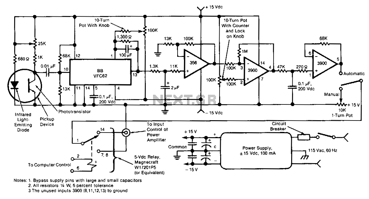
This electronic motor-speed control circuit is designed to operate in an electrically noisy environment. The circuit includes an optoelectronic pickup device, which is placed inside the motor housing to provide a speed feedback signal. The circuit automatically maintains the...
A typical device that requires less than 5v and draws less than 25mA is an LED. A LED must be supplied with an exact voltage for it to operate correctly. Because it requires LESS than 5v, a dropper resistor...
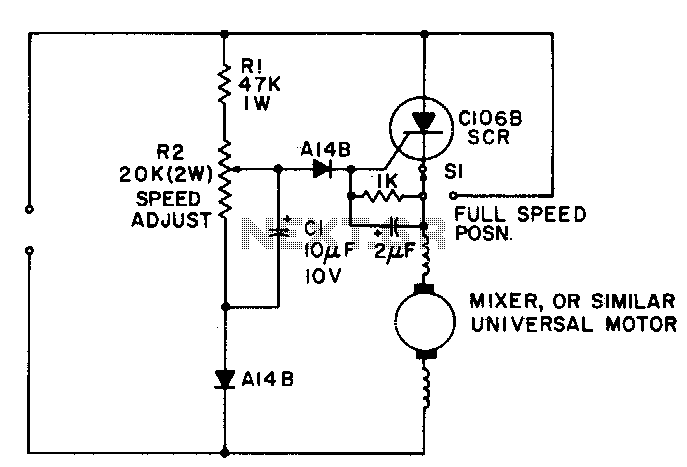
A simple half-wave motor speed control is effective for use with small universal (AC/DC) motors, featuring a maximum current capability of 2 amps RMS. The control provides speed-dependent feedback, ensuring excellent torque characteristics for the motor, even at low...
Modern exhibitions utilize extensive sound, light, and electrical technologies for advertising, promotion, and propaganda. This involves various electrical diagrams and control models. Commonly used is an automatic program circuit with pre-recorded commentary, which requires synchronization of two mating times....
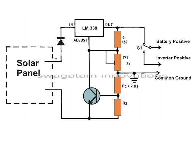
Solar panels are well-known devices that convert solar energy or sunlight into electricity. A solar panel consists of discrete sections of individual photovoltaic cells, each capable of generating a small amount of electrical power, typically between 1.5 to 3...
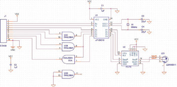
This example illustrates the process of stacking layers and designing transmission lines for a high-speed digital printed circuit board (PCB). It also shows how to create a moated ground area with a bridge around a high-frequency crystal oscillator, perform...