
Amproluck W850ES microwave auto-sensing electronic microwave circuit diagram

The described circuit comprises several essential components that work together to ensure safe and efficient operation of a heating system, likely for an industrial application.
The XP power plug serves as the primary power input, delivering electrical energy to the circuit. The FU fuse is included for overcurrent protection, preventing damage to the circuit in case of a fault. The ST temperature control regulates the operating temperature of the system, ensuring it remains within safe limits.
Low-voltage transformers (T1) convert the mains voltage to a lower level suitable for use by other components. The door interlock switches (S1, S2) ensure that the system cannot operate unless the doors are securely closed, enhancing safety. The S3 threshold control switch may be used to set operational limits for the system, triggering different actions based on temperature or other parameters.
The RT thermal sensor monitors temperature and provides feedback to the control system, allowing for adjustments based on real-time conditions. The K1 and K2 relays act as switching elements that control the power to various components based on signals received from the control logic.
The EL furnace light indicates when the system is operational, providing visual feedback to the user. The M1 wheel motor and M2 fan motor are responsible for mechanical movement and airflow, respectively, essential for maintaining efficient heating and cooling cycles.
The high-voltage transformer (T2) steps up the voltage for the magnetron (MT), which generates microwave energy for heating applications. The high voltage capacitor (C) stores electrical energy for discharge, supporting the operation of the magnetron. Protection is provided by the V1 protection diode and the V2 high voltage diode, which safeguard the circuit from voltage spikes and ensure proper current flow.
This schematic illustrates a comprehensive design that integrates safety features, temperature control, and efficient power management, making it suitable for various heating applications.XP-power plug, FU-fuse, ST-temperature control, T1-low-voltage transformers, S1, S2-door interlock switch, S3-threshold control switch, RT-thermal sensor, K1, K2-relay, EL- furnace light, M1-wheel motor, M2-fan motor, T2-high-voltage transformer, C-high voltage capacitor, V1-protection diode, V2-high voltage diode, MT-magnetron.. 🔗 External reference
Related Circuits
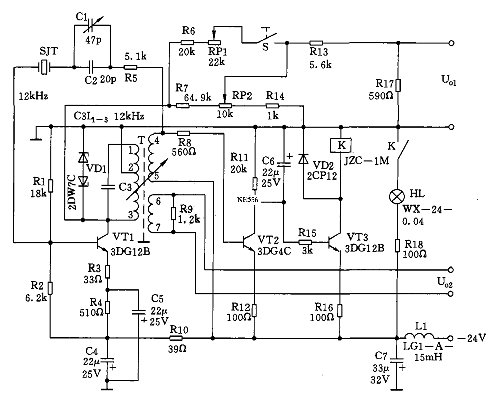
The circuit features a 12kHz intermediate frequency (IF) oscillator utilizing a quartz crystal for precision frequency generation. It includes components for output level adjustment, a level-up circuit, and an alarm circuit. The design employs a unique single-tuned variable feedback...

It is a self-oscillating voltage booster. It is relatively simple to build and it will allow you to use almost all the power in the battery, even when its voltage is low. The self-oscillating voltage booster is a circuit designed...
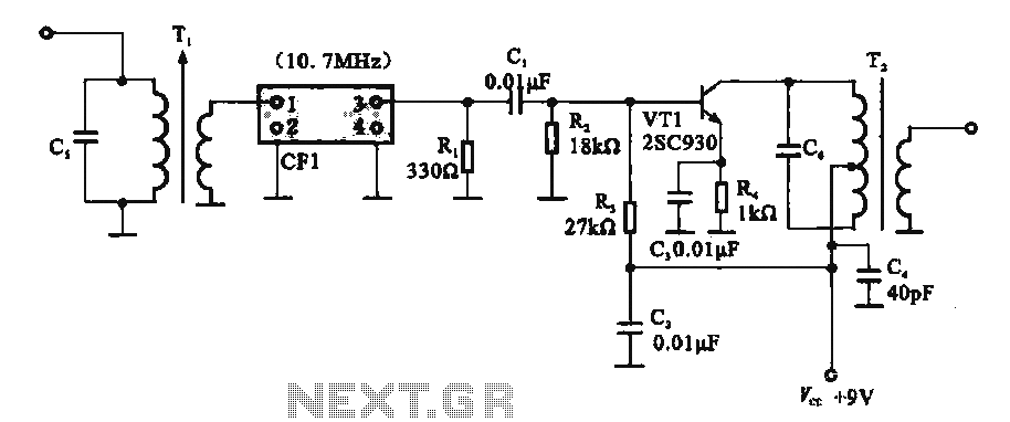
This circuit features a ceramic filter integrated with an FM intermediate frequency (IF) amplifier. The FM IF amplifier circuit primarily consists of an input variable voltage regulator (T), ceramic filters (CF1), and additional components such as the IF amplifier...

This is a simple design of an audio level meter. The circuit utilizes a single integrated circuit (IC) and a minimal number of external components. It is based on the LM3915, which functions as the controller for the audio...
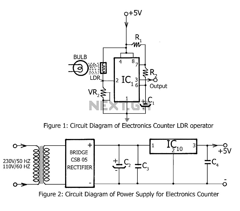
Simple counting can be performed by anyone, but counting over large intervals can be tedious and prone to errors. A previously published project, the Digital Counter, serves as a foundation for this electronics counter, which is the second project...
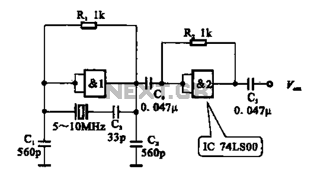
A crystal oscillator circuit comprises various gates as illustrated in the provided figures. Figure (A) represents a crystal oscillator circuit operating at 1 MHz, while figure (B) depicts a 20 MHz crystal oscillator circuit. Figure (C) shows a variable...