
Electronic counter
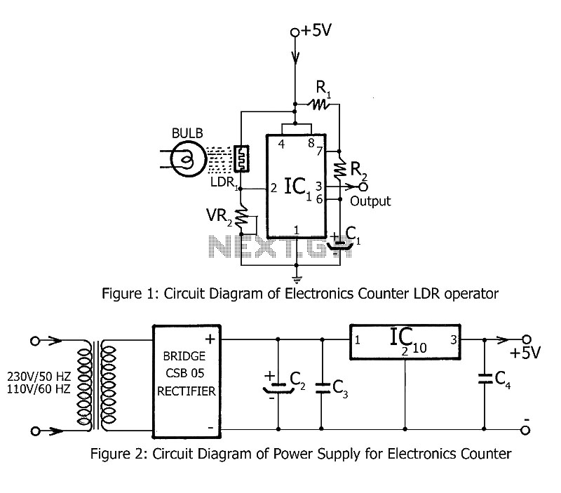
The electronics counter circuit is designed to automate the counting process, minimizing human error during large interval counting. The use of TTL ICs enhances the reliability and speed of the circuit compared to CMOS counterparts, allowing for faster switching and lower propagation delays. The heart of the counting mechanism lies in the interaction between the LDR and the NE555 timer, which serves as a pulse generator.
When an object passes between the light source and the LDR, it interrupts the light beam, causing the LDR's resistance to change. This change triggers the NE555 timer to produce a negative square wave output. The frequency of this output correlates directly with the rate at which objects are counted. The square wave signal is fed into IC2, a binary counter, which counts the pulses generated by the NE555 timer. Each pulse increments the count displayed on the seven-segment displays.
The cascading connection of the counters (IC2 to IC3, IC3 to IC4, IC4 to IC5) allows for counting beyond single digits, enabling the display of numbers up to 10,000 across the four displays. The BCD to 7-segment latch decoder drivers (IC5 and IC6) convert the binary-coded decimal output from the counters into a format suitable for the seven-segment displays, ensuring clear and readable output.
The inclusion of a reset switch (SW1) allows users to easily reset the counter, bringing it back to a known state of 0000. This feature is particularly useful in applications where counting needs to be restarted frequently, providing flexibility and ease of use. Overall, this electronics counter circuit effectively combines various components to create a reliable, user-friendly counting solution suitable for a range of applications.Simple counting can be done by anyone but counting in interval up to large number is tedious and the chance of forget is maximum. As, we have already published Counter Circuit | Digital Counter. Now, here electronics counter is second project by dreamlover technology in the series of counting based project.
Bothe the counting circuit published i n this website counts up to 10, 000 with the help of four seven-segment displays. The difference is previous circuit utilize CMOS ICs where the electronics counter use TTL ICs. The input circuit consists of LDR following by negative square wave generator circuit build around Timer IC (NE555). A bulb is used here as light source focused on LDR. The property of LDR is that whenever the light focused on base of LDR is obstructed, it gives trigger and square wave is generated and given as input signal to counter circuit.
So the objects to be counted are arranged in a row to move one by one in between the light source and the LDR. IC2 shows any number between 0-9 according to input square wave given to pin no 14. After each negative pulse a carrying pulse is produced by decoder IC and given to another one (i. e. from IC2 to IC3, IC3 to IC4, IC4 to IC5 ). IC5 and IC6 is BCD to 7-segment latch decoder driver. The reset switch SW1 is used to reset the electronics counter to 0000 states. 🔗 External reference
Related Circuits
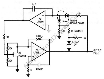
This is a quartz-stabilized oscillator circuit with electronic gain control. Replacing the common filament lamp for amplitude stabilization, this circuit uses... This circuit represents a quartz-stabilized oscillator featuring electronic gain control, which enhances the stability and precision of the output...
The circuit is designed to operate with an audio power amplifier that uses 18V-0V-18V power rails. The specific voltage is not critical, but the feedback is referenced to an LED chain connected to a 12V rail, necessitating a separate...

Each bistable circuit comprises two oppositely-symmetrical germanium transistors, two diodes, and four resistors. An additional transistor, Q, facilitates the transition of the conducting state to the next position when actuated by a transfer pulse. The absence of capacitors allows...
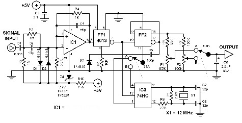
This frequency counter utilizes an existing digital multimeter (DMM) as the display unit, allowing for a low-cost construction. Due to the high impedance characteristic of most DMMs, a frequency-to-voltage converter can be easily connected without matching issues. The converter...
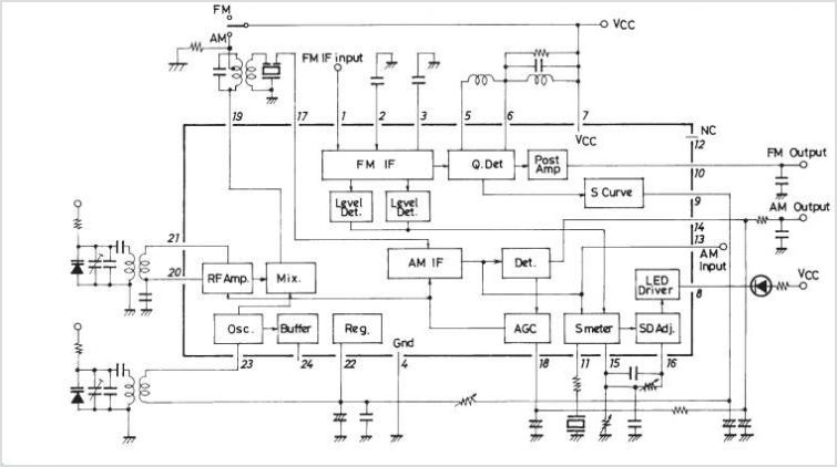
The LA1600 is an AM tuner integrated circuit (IC) housed in a 9-pin single in-line package (SIP). It provides the functionality of an AM tuner and is capable of operating within the shortwave (SW) band range. This IC is...
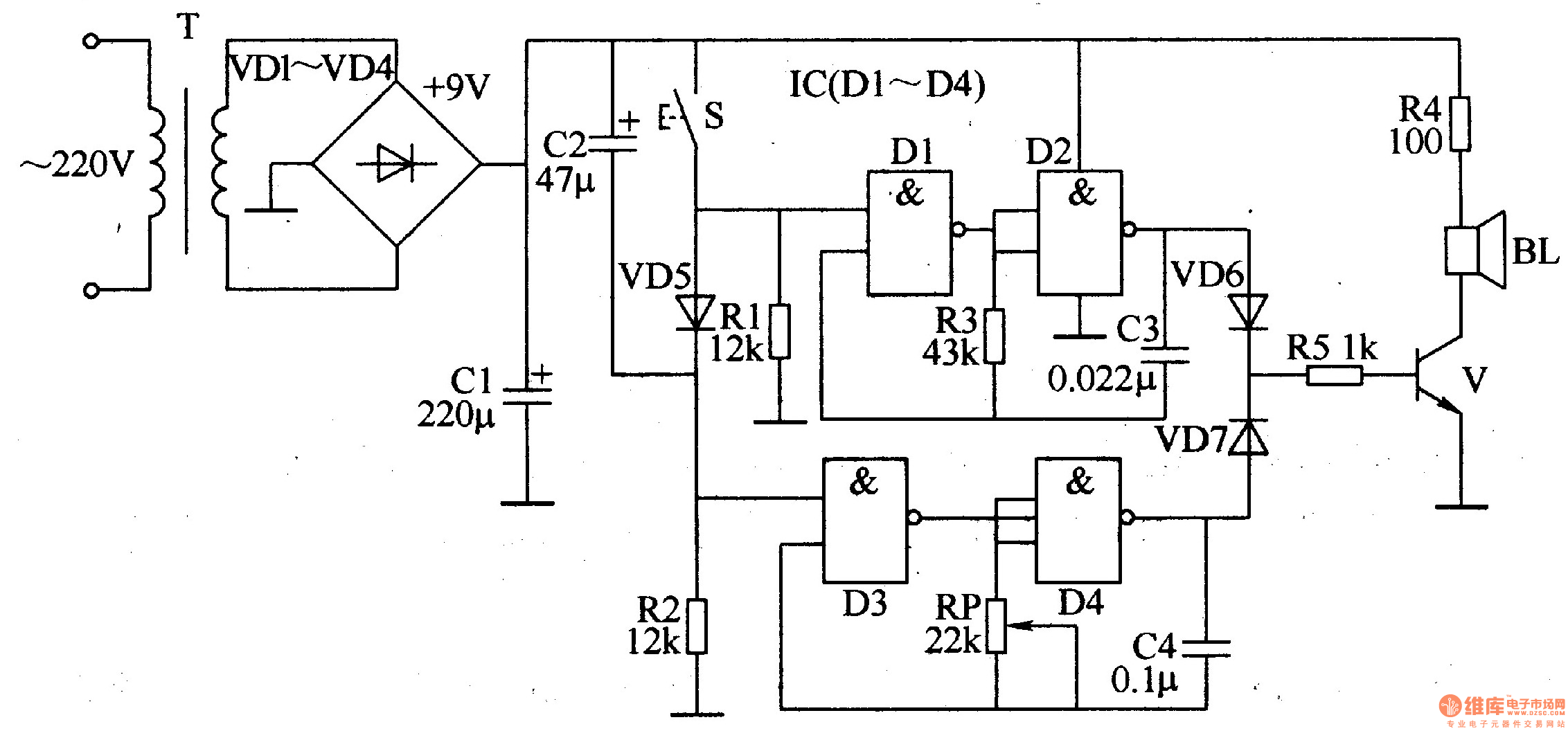
The ding-dong electronic doorbell circuit consists of a power supply circuit, a trigger control circuit, and an audio oscillator output circuit. The power supply circuit includes a power transformer (T), rectifier diodes (VD1-VD4), and a filter capacitor (C1). The...
Warning: include(partials/cookie-banner.php): Failed to open stream: Permission denied in /var/www/html/nextgr/view-circuit.php on line 713
Warning: include(): Failed opening 'partials/cookie-banner.php' for inclusion (include_path='.:/usr/share/php') in /var/www/html/nextgr/view-circuit.php on line 713