
An Anemometer Circuit
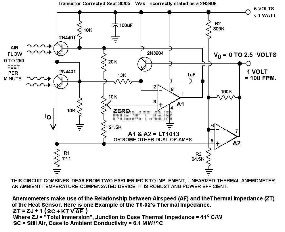
The circuit board in question is designed to handle a specific application, likely related to measuring or controlling wind flow, as inferred from the mention of wind flow accuracy. The primary function of the board is to ensure stable operation, which is critical for accurate readings and consistent performance in such applications.
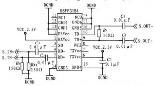
At the heart of the circuit board is a 5 Volt voltage regulator, which is essential for providing a stable power supply. This regulator takes a higher input voltage and outputs a constant 5V, which is necessary for the reliable operation of various electronic components on the board. The choice of a 5 Volt regulator indicates that the circuit likely utilizes common components such as microcontrollers, sensors, or other integrated circuits that require this voltage level.
The design may include additional features such as bypass capacitors connected to the output of the voltage regulator to filter out noise and provide transient response improvements. This ensures that the voltage supplied to sensitive components remains stable even during load changes.
The circuit may also incorporate input and output terminals for easy connection to external devices or sensors. If wind flow measurement is the primary function, it is probable that the board interfaces with a flow sensor, which could be based on various technologies such as anemometers or pitot tubes, depending on the required measurement accuracy and application.
Furthermore, the layout of the circuit board should be optimized for minimal interference and maximum signal integrity. This might involve careful placement of components, routing of traces, and possibly the inclusion of ground planes. Such considerations are vital for applications where precision is paramount.
In summary, the circuit board is a carefully designed assembly intended to provide stable power and facilitate accurate measurements, particularly in the context of wind flow, while ensuring reliability and performance through the use of a 5 Volt regulator and thoughtful design principles.I designed up this circuit board because of a request from a visitor to my website. I also assemble the circuit board to Varify the board was correct. It does work, VERY NICELY, but I have no way to varify the accuracy of wind flow that is stated by the author. Since the Circuit Requires a Stable Supply, I have added a 5 Volt Regulator to the Circuit Board. 🔗 External reference
Related Circuits
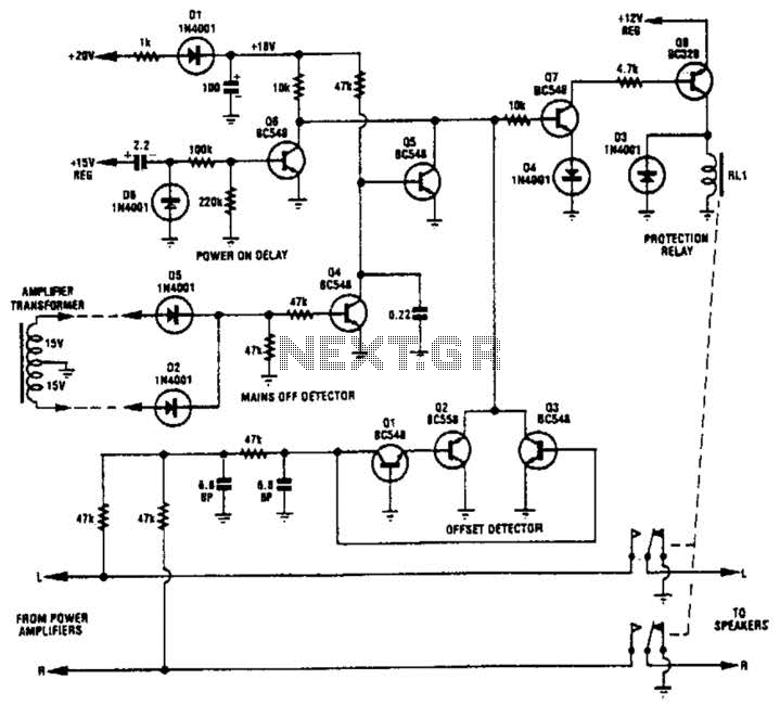
Transistors Q1, Q2, and Q3 monitor the two outputs of the stereo amplifier. If the offsets exceed 2 V, Q7 is turned off, which in turn deactivates Q8 and the normally on relay. Diodes D2 and D5, along with...
Automatic color holiday lights circuit The automatic color holiday lights circuit is designed to control the operation of decorative lights during festive seasons. This circuit typically utilizes a microcontroller or a timer to manage the sequencing and color changes...
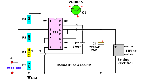
This AC to DC power supply can output 5A in continuous operation and 12A peak current. This type of DC power supply uses a PCB, allowing for two case types. The described AC to DC power supply is designed to...
An article previously discussed connecting to the Raspberry Pi board from a Linux PC using the serial port. This time, the focus is on how to achieve the same connection using a Windows PC. In this case, a Windows...
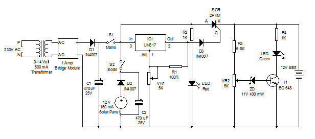
Battery charger utilizing solar and electrical power with a circuit diagram. This dual power source battery charger can charge a lead-acid battery using two different power sources. The battery charger circuit is designed to efficiently charge a lead-acid battery by...

Connect the components, ensuring to pay attention to the connections for the transistor. The 22-ohm load resistor and thermistor should be connected in a manner that allows for good thermal contact. Note: If using the Light Application Adapter, REFIN-...
Warning: include(partials/cookie-banner.php): Failed to open stream: Permission denied in /var/www/html/nextgr/view-circuit.php on line 713
Warning: include(): Failed opening 'partials/cookie-banner.php' for inclusion (include_path='.:/usr/share/php') in /var/www/html/nextgr/view-circuit.php on line 713