
Battery Charger using Solar & Electrical Power with circuit diagram
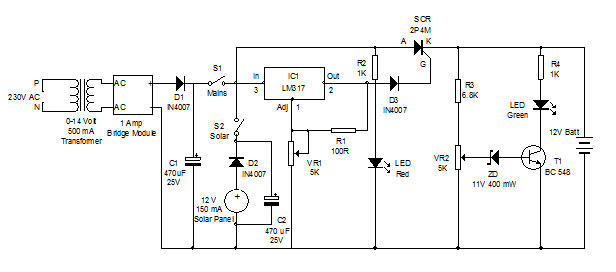
The battery charger circuit is designed to efficiently charge a lead-acid battery by integrating both solar and electrical power sources. The schematic typically includes a solar panel, a rectifier, a charge controller, and a battery management system.
The solar panel converts solar energy into electrical energy, which is then directed to a rectifier circuit. This rectifier, often composed of diodes, converts the generated direct current (DC) from the solar panel into a usable form for charging the battery. The charge controller is a critical component that manages the voltage and current coming from both the solar panel and the electrical power source, ensuring that the lead-acid battery is charged at the appropriate rate without overcharging or damaging it.
In addition to the solar input, the circuit includes an option for connecting an electrical power source, such as a wall outlet. This feature allows for continuous charging of the battery, even when solar energy is insufficient, such as during cloudy days or at night. The dual power source design enhances the reliability and versatility of the charging system.
The battery management system monitors the state of charge of the lead-acid battery, providing protection against over-voltage, under-voltage, and over-temperature conditions. This ensures the longevity and safety of the battery during the charging process.
Overall, this dual power source battery charger circuit is a practical solution for renewable energy applications, combining solar energy with conventional electrical power to maintain battery health and performance.Battery Charger using Solar & Electrical Power with circuit diagram. This Dual Power Source battery charger can utilize two power sources to charge a Lead Acid battery 🔗 External reference
Related Circuits
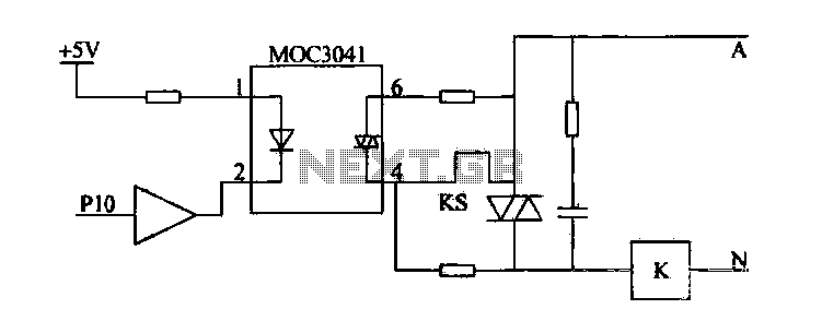
Device for an intermediate relay. The circuit utilizes a Triac AC contactor interface, employing the MOC3041 Triac output optical coupler to trigger the Triac. When Pl0 is low, the Triac will be activated, energizing the AC contactor coil. The described...
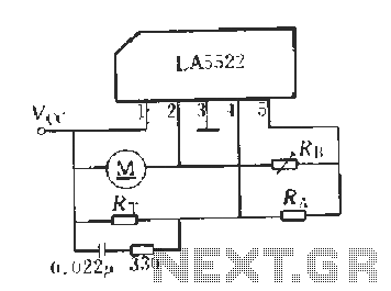
LA5522 Application Circuit. It operates as follows: When the supply voltage (Vcc) changes due to mechanical loads or negative changes, the motor speed may vary. The speed is proportional to the anti-electric potential (E), which also causes changes in...
Tro telephones can be utilized as an intercom through the implementation of this circuit. Traditional rotary phones, particularly those that are non-electronic, may be the most effective for this purpose. Additionally, this method can also power handsets alone. The circuit...
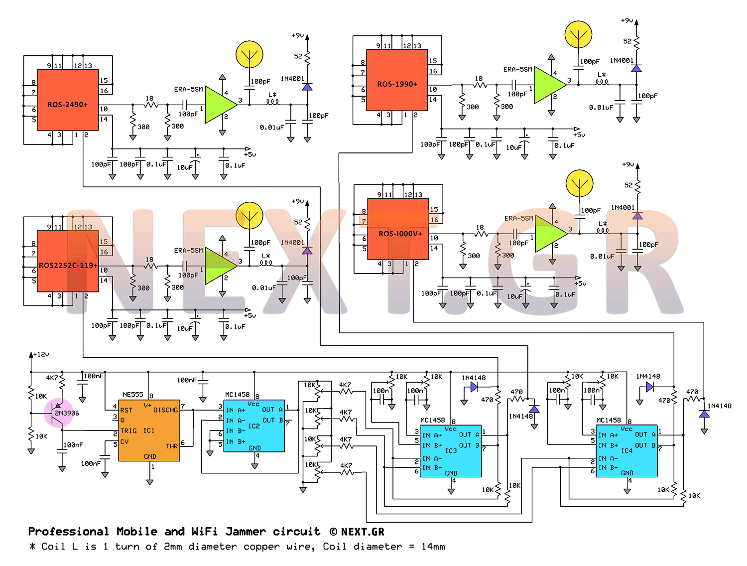
This jammer circuit can be utilized both indoors and outdoors, providing a coverage range of approximately 30 meters to disconnect wireless devices from their communication with the base station. The circuit design employs frequency ranges allocated to mobile operators,...
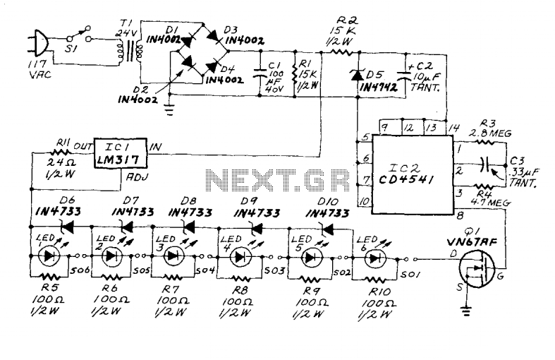
An LM317 voltage regulator is configured as a constant-current source to supply a 50 mA charging current to S01-S06, which is an array of AA-cell battery holders. Each battery holder is connected in series with an LED and its...
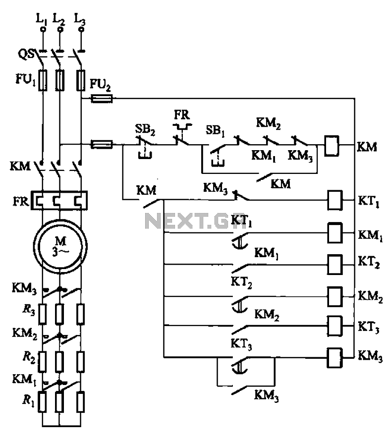
The circuit depicted in Figure 3-159 employs complementary operation three times along with three relay contacts. This is followed by the automatic elimination of the rotor circuit resistance levels, ultimately reducing the rotor winding variable resistor to zero (fully...