
PID Temperature Control circuit schematic

The circuit involves a transistor acting as a switching element, which is critical for controlling the temperature in a hatching environment. The 22-ohm load resistor is used to limit the current flowing through the circuit, protecting sensitive components from excessive current. The thermistor, a temperature-sensitive resistor, provides real-time temperature readings, which are essential for maintaining optimal conditions for hatching chicks.
Proper thermal contact between the thermistor and the load resistor is vital for accurate temperature readings. This ensures that the thermistor can detect temperature changes effectively, allowing the control system to respond to variations promptly. The connection to AGND through the Light Application Adapter simplifies the circuit design by ensuring that the reference voltage is stable, which is crucial for accurate analog measurements.
When connecting directly to the EMANT300, it is important to establish the REFIN- connection to AGND to prevent erroneous readings from the analog inputs. This connection allows the internal reference voltage to function correctly, which is necessary for the precise operation of the PID (Proportional-Integral-Derivative) control algorithm used in the Temperature Control for Hatching Chicks VI. This VI serves as a diagnostic tool to confirm that the circuit is constructed correctly and operates within the expected parameters.
In summary, careful attention to the connections and component placement is essential for the successful implementation of this temperature control circuit, ensuring optimal performance in hatching applications.Connect the components. Take note of the connections for the transistor. Connect the 22 ohm load resistor and thermistor in a way that they make good thermal contact. Note: If you are using the Light Application Adaptor, REFIN- is already connected to AGND. If you are connecting directly to the EMANT300, it is important that this connection is mad e, otherwise your analog input measurements will be wrong. This connection allows the internal reference to be connected correctly. Open Temperature Control for Hatching Chicks. vi from the PID Temperature Control folder. You will use this VI to verify that your circuit is built correctly. 🔗 External reference
Related Circuits
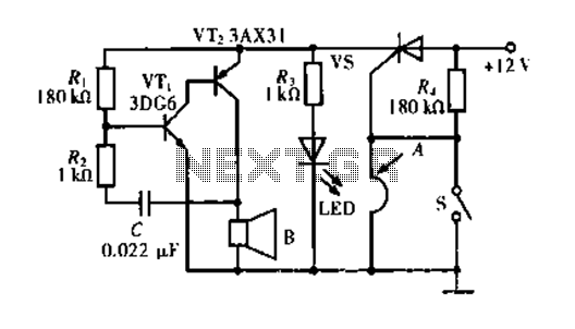
The circuit operates based on a principle where the SCR (Silicon Controlled Rectifier) trigger is grounded, keeping it in the off state. When a burglar triggers the alarm, a voltage is supplied to the SCR trigger, turning it on....
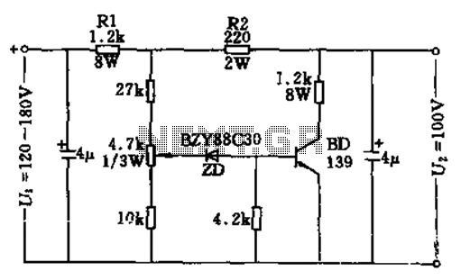
The circuit features no-load and short circuit protection mechanisms. To accommodate short circuit conditions, it is necessary to increase resistors R1 and R2 to allow for power dissipation; for example, R1 can be set to 1.2kΩ with a power...
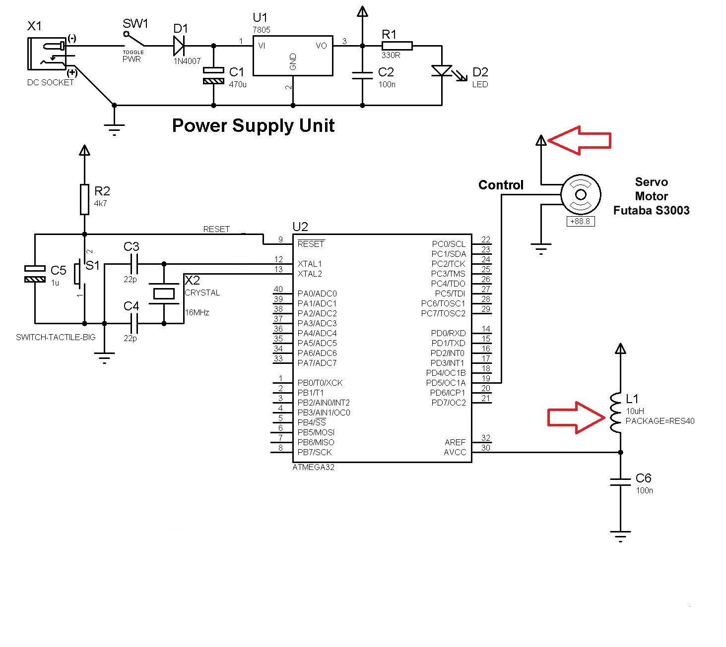
Good preparation. There is one suggestion to use RFM70 or RFM22 for RF communication. The RFM70 and RFM22 are low-power, high-performance RF transceiver modules designed for wireless communication applications. Both modules operate in the 2.4 GHz ISM band, making them...
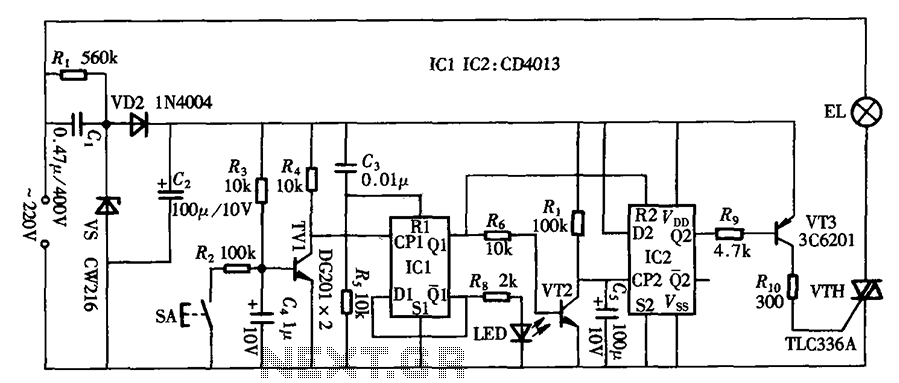
The circuit primarily utilizes a touch-delay switch composed of a pair of D flip-flops (CD4013). It can be employed in power switch applications for various machines. The delay switch can also function as a lighting control and features a...
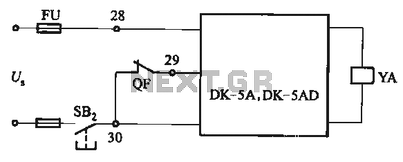
The DK-5A and DK-5AD AC power control circuit is illustrated in Figure 6-77. The figure includes a closing button (SBz) and a line (YA) connected to the closing electromagnet coil (U). This circuit is designed for the operation of...

At the core of the CD4-MX is an astable multivibrator, constructed using transistors Q1 and Q2, which drives step-up transformer T1. The output from T1 is rectified by diodes D3 to D6 and utilized to charge capacitor C4. Upon...