
An Expandable Multi-Zone Modular Burglar Alarm circuit
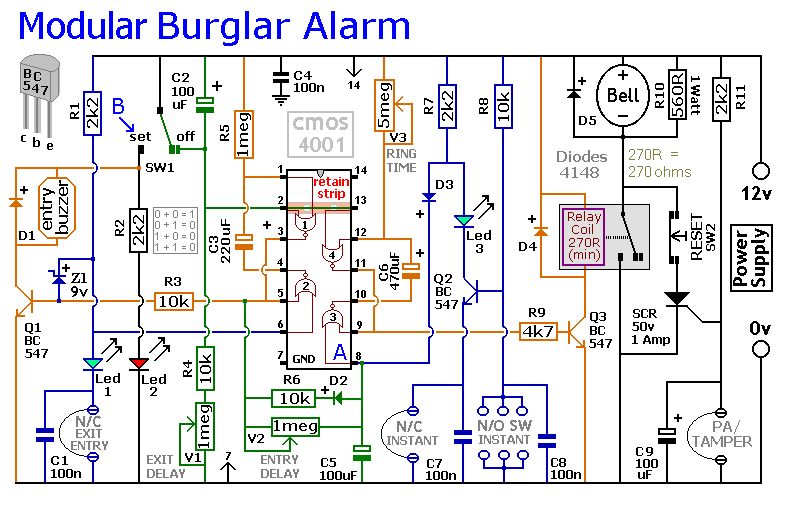
The described circuit is designed to enhance security systems by providing a structured approach to alarm management. The automatic exit and entry delays are crucial for allowing users to enter or exit a secured area without triggering an alarm immediately. This feature is particularly useful in residential and commercial security applications where users may need a brief period to deactivate the system upon entry or activate it upon exit.
The timed bell cut-off feature serves to limit the duration of alarm sounds, thereby preventing unnecessary disturbances. This is particularly important in environments where false alarms may occur, as it reduces the likelihood of alarm fatigue among residents or occupants.
Support for both normally-closed and normally-open contacts enhances the circuit's versatility, allowing it to be compatible with a wide range of sensors and devices. Normally-closed contacts are typically used in security applications to detect circuit interruptions, while normally-open contacts can be used for various triggering mechanisms.
The inclusion of a 24-hour personal attack/tamper zone is a significant feature for personal safety. This zone remains active at all times, providing immediate response capabilities in the event of a tampering incident or personal attack, thereby enhancing the overall security of the system.
The ability to integrate expansion modules is a key advantage of this circuit design. This modularity allows for scalability, enabling users to customize their security system according to specific needs. Additional zones can be added seamlessly, accommodating various sensor types, including inertia or shock sensors that detect physical disturbances. This flexibility makes the system suitable for a wide range of applications, from residential properties to commercial establishments, ensuring comprehensive coverage and enhanced security measures.This circuit features automatic Exit and Entry delays and a timed Bell Cut-off. It has provision for both normally-closed and normally-open contacts, and a 24-hour Personal Attack/Tamper zone. By using the Expansion Modules, you can add as many zones as you require; some or all of which may be the inertia (shock) sensor type..
🔗 External reference
Related Circuits

Circuit characteristics: A simple phase shift range of 180 degrees, with a practical range of 170 degrees. The circuit is influenced by temperature and is suitable for small power applications in less demanding situations. The circuit operates by utilizing a...

This audio distribution electronic project circuit diagram is designed using the TL064 or TL06 operational amplifiers and some other common electronic parts. The audio distribution circuit utilizes TL064 or TL06 operational amplifiers, which are quad op-amps known for their low...
This simple and inexpensive circuit built around a popular CMOS hex inverter IC CD4069UB offers four sequential switching outputs that may be used to control 200 LEDs (50 LEDs per channel), driven directly from mains supply. Input supply of...
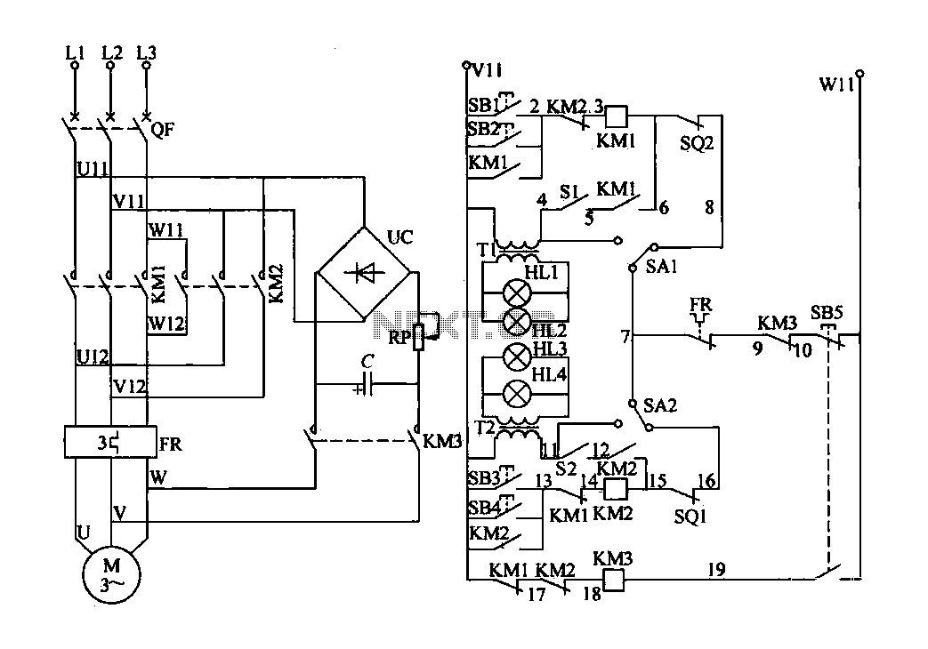
The electric valve control circuit consists of three main parts: the main lines, control lines, and power consumption brake line. The main circuit includes a power switch (QF), three-phase AC contactors (KM1, KM2), a thermal relay (FR), and a...
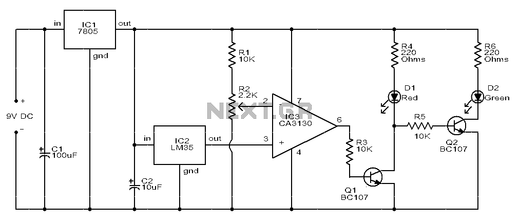
The circuit consists of two light-emitting diodes (D1 and D2) whose operation is controlled by the ambient temperature. A temperature sensor, the LM35, generates an output of 10 mV for each degree of temperature increase. A reference potentiometer, R2,...
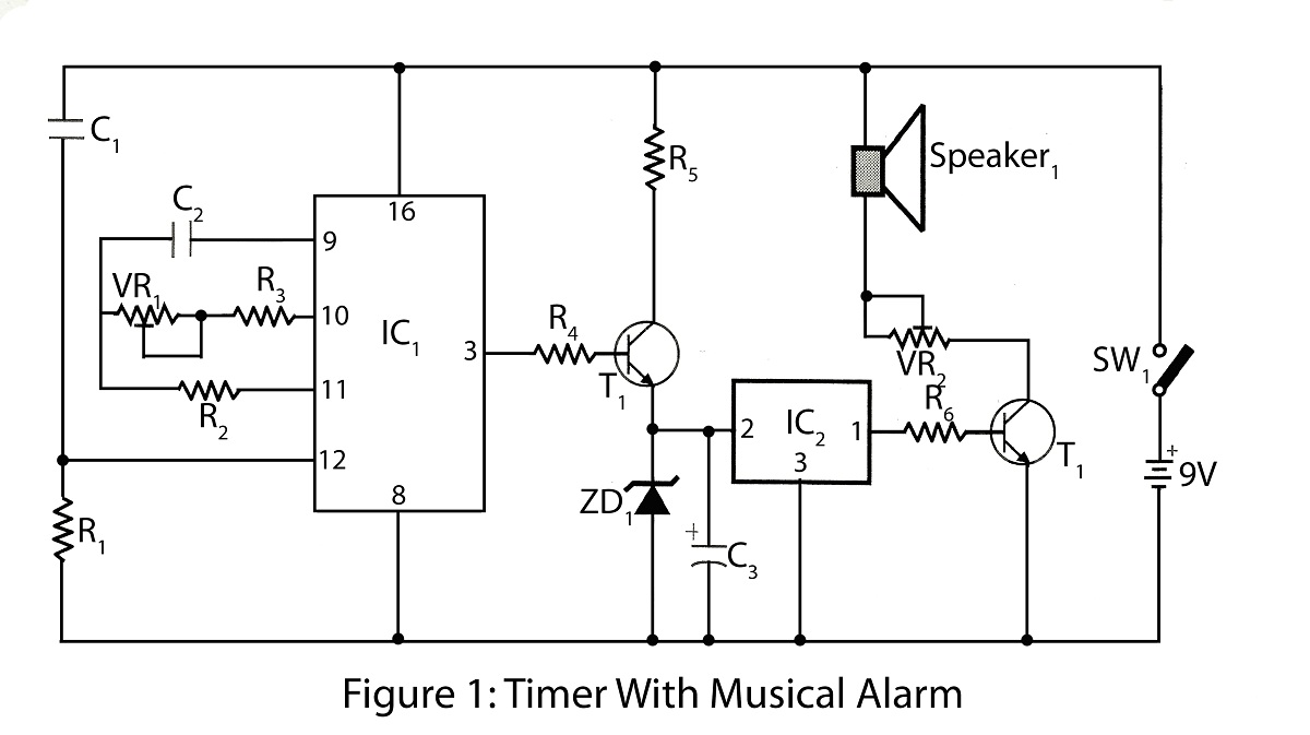
The timer with a musical alarm is an electronic timer project utilizing the CD4060 integrated circuit. It provides a delay ranging from 1 minute to 2 hours. The circuit diagram for the timer with a musical alarm is part...