
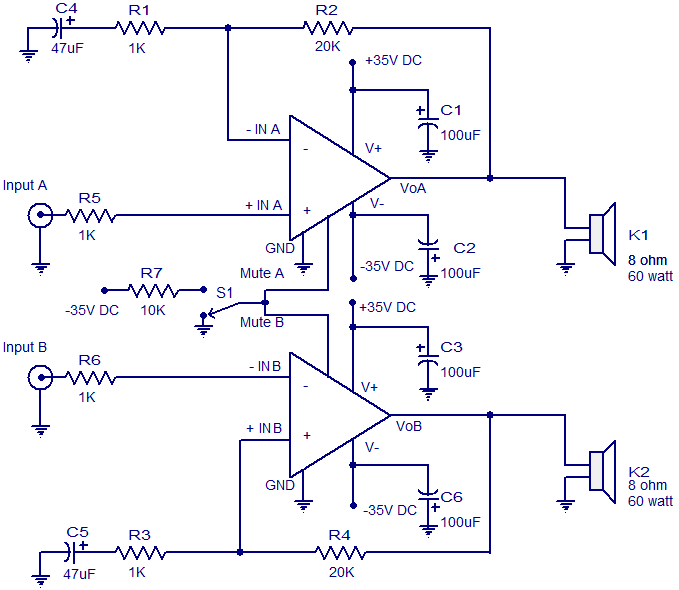
Audio distribution electronic project circuit diagram
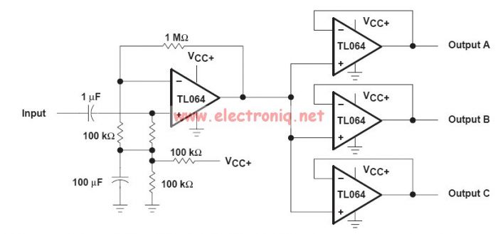
The audio distribution circuit utilizes TL064 or TL06 operational amplifiers, which are quad op-amps known for their low noise and high performance. These components are ideal for audio applications due to their ability to amplify weak audio signals without introducing significant distortion or noise. The circuit typically includes a power supply section, input and output stages, and feedback networks to ensure stability and gain control.
The design may incorporate resistors and capacitors to set the gain of the operational amplifiers and to filter out unwanted frequencies. Input connections can be made for various audio sources, while output connections are designed to drive speakers or further processing stages. The layout should ensure minimal interference and optimal signal integrity, often achieved through careful routing of traces and placement of components.
For practical implementation, a PCB (Printed Circuit Board) can be designed to accommodate all components, ensuring a compact and reliable assembly. Proper grounding techniques should be employed to minimize noise and improve overall performance. Additionally, consideration should be given to the thermal management of the op-amps, as excessive heat can affect their operation.
Overall, this audio distribution circuit is suitable for applications in home theaters, public address systems, and musical performance setups, providing high-quality audio signal distribution with minimal loss and distortion.This audio distribution electronic project circuit diagram is designed using the TL064 or TL06 operational amplifiers and some other common electronic parts. 🔗 External reference
Related Circuits

This circuit is a compact timer designed to keep the headlights of a car illuminated for approximately 1.5 minutes before automatically turning them off. By integrating this circuit into a vehicle, users can access dark areas without the need...
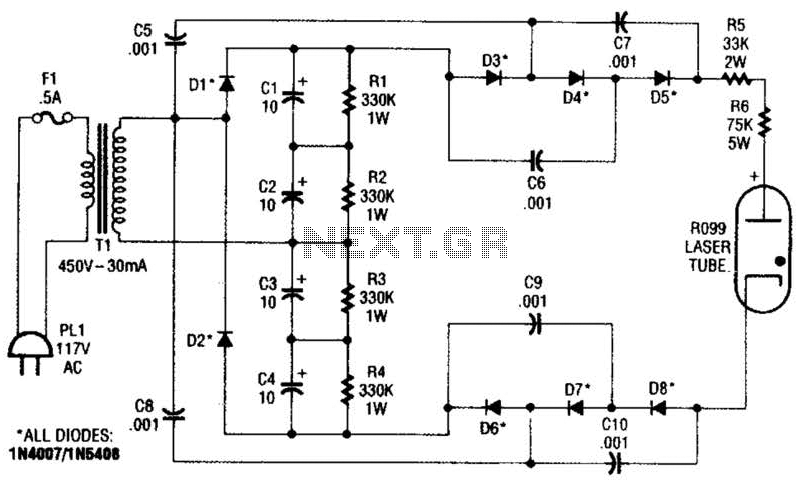
This supply generates an initial high voltage for ignition purposes. After ignition, the supply generates about 1300 to 1500 V. If a higher ignition voltage (than the 6000 V supplied) is necessary, more multiplier stages can be added to...
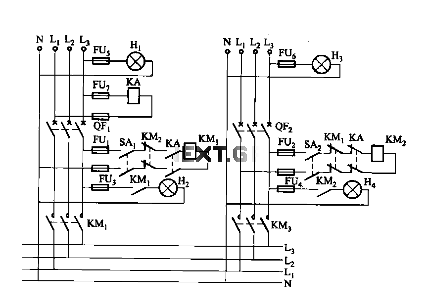
Dual power automatic recovery means one power supply and one standby power supply. When the main power supply is turned off, the standby power supply is automatically activated. Once the main power supply is restored, the system automatically exits...
High Power Siren Circuit. This article discusses a robust siren circuit suitable for various applications. A complementary transistor pair (BC557 & BC337) is configured as an oscillator to directly drive the speaker. Transistor Q1 (BC557) is utilized to ensure...
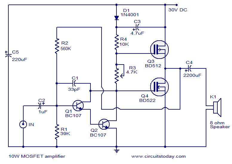
This article lists various types of audio amplifier circuits using MOSFETs. All circuits have been tested in a laboratory environment and have shown satisfactory performance. The amplifier utilizes one transistor, two MOSFETs, and a few resistors and capacitors in...
The circuit diagram presented is for a 2 x 60 Watt stereo amplifier utilizing the LM4780 from National Semiconductors. The LM4780 is an excellent audio amplifier integrated circuit capable of delivering 60W RMS power output per channel into 8-ohm...