
Electric valve motor control circuit
The electric valve control circuit is designed to manage the operation of a valve motor through a combination of control and power circuits. The main circuit includes essential components such as a power switch (QF) that allows for manual control of the entire system. The three-phase AC contactors (KM1 and KM2) are critical for switching the power to the motor, while the thermal relay (FR) provides protection against overheating.
The control circuit is composed of multiple control buttons (SB1-SB5) which facilitate user interaction for opening or closing the valve. Each button is linked to a specific AC contactor (KM1 or KM2) and their auxiliary contacts, enabling precise control over the valve's operation. The power transformers (T1 and T2) step down the voltage to suitable levels for control circuit components, while the signal indicating lamps (HL1-HL3) provide visual feedback on the operational status of the valve.
The inclusion of flash switches (S1 and S2) enhances the visibility of the control signals, ensuring that operators can easily identify the state of the system. The state selector switch (SA1, SA2) allows for the selection between different operational modes, determining whether the valve is in a controlled or uncontrolled state.
Position switches (SQ1 and SQ2) are integrated into the circuit to provide feedback on the valve's position, ensuring that the motor is deactivated when the valve reaches its fully open or closed positions. This feature is crucial for preventing damage to the motor and valve due to over-travel.
Furthermore, the fixed line components such as the bridge rectifier (UC) and energy storage capacitor (C) are essential for converting AC to DC for the control circuit and providing the necessary energy for braking the valve motor. The limiting potentiometer (RP) allows for the adjustment of braking current, enabling fine-tuning of the motor's stopping characteristics.
The selection of the energy storage capacitor is based on the power rating of the valve motor. For motors rated at 2 kW or less, capacitors in the range of 100-200 µF are suitable, while motors rated between 2-5 kW require larger capacitors of approximately 400 µF. It is also recommended that the capacitor voltage rating be at least 600V to ensure reliability under operational conditions.
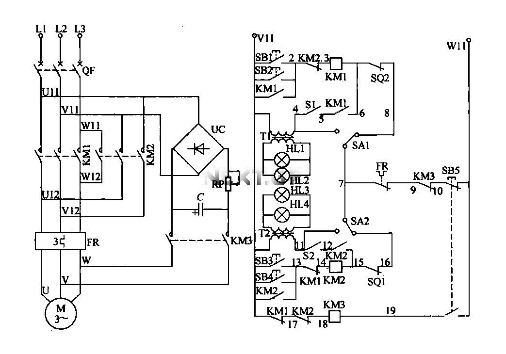
This comprehensive design ensures efficient control of the valve motor, maintaining operational safety and reliability while providing operators with clear feedback on system status.Electric valve control circuit consists of the following three parts: main lines, control lines, and power consumption brake line aa. The main circuit includes a power switch v iews. QF, three-phase AC contactor KM1, KM2 main contact, thermal relay FR element of clarity and three-phase AC motor and so on. The control circuit includes a control button SB1-SB5, AC contactor KMl-KM3 line BH and their auxiliary contacts, power transformer Tl, T2, the signal indicating lamp HL1-HIA, flash switch Sl, S2, state selector switch SA1, SA2 and a position switch sQl, SQ2 like.
Fixed line Pina energy package includes a bridge rectifier uc, limiting potentiometer RP, the energy storage capacitor C and AC contactor KM3 main contact and the like. Electric valve motor control circuit shown in Figure 4-35. When the line is in hot standby, you can choose SA1, SA2 switch position to determine the main lines of controlled or uncontrolled.
When SA1 (SA2) located on the left when, KMl (KM2) coil exit. When running t SAl (SAZ) on the right when, KMl (KM2) coil put into operation, when the SA1 (SA2) on the left, the signal lamp is lit, the operator or maintenance personnel can use this file to check the control circuit is obtained l when the electric SA1 (Xu address) on the right, the signal light is off, only after the motor starter valve, signal lights HL1, H12 (HL3:., HIA) will flashing light. Close the power switch QF, the selector switch SA1 is placed to the right, press the SB1 (or SB2), a current flows through Vll SBl (or SB2) a KM2 contacts (2-3) a KM1 coil --s02-- SAl - FR contact (7-9) --KM3 contacts (9-10) a SB5 a Wll.
KM1 coil is energized from operation and magnesium, the valve motor is rotated to open the valve. In the KM1 after contact (5-6) is turned on, the flash switch sl work, red light green light HL1 and HL2 used as a flash indication. When the valve is opened to limit position, SQ2 off, KM1 coil power failure, the main contact reset valve Rongji electric power is turned off, the valve motor to stop working.
The selector switch SA2 placed to the right, press the SB3 (or SB4), according to the current shake through Vll a SB3 (~ aSB4) - * KMl contact (13-14) --- KM2 coil -, - SQl- * SAZ a FR contact (7-9) a KM3 contact (9-10) -SB5 a Wll, KM2 coil is energized from the merger chain f kitchen door motor is rotated to close the valve. After KM2 contacts (12-15) is turned on, the flash switch S2 work, HL3 red and green flashing fflA for instructions.
When the valve is closed to the limit position, the position switch sQl off. KM2 coil power failure, the main contact is reset, the valve motor power supply is turned off. If the valve is opened from the group process, press the stop button when the barrier can SB5, its being broken off contact so that KM1 or KM2 coil power loss curve release, motor lost power. Simultaneously. SB5 moving together contacts (19-W11) is closed. KM3 coil is energized, the contact (9-10) off - to prevent malfunction KM1 or KM2, KM3 main contact is closed, and the output capacitor energy storage, while the role of a bridge rectifier to the motor windings, brake torque, the motor stops instantaneously.
Thus, you can make the same door as required to stop accurately to the specified location. Figure 4-35 potentiometer RP from limiting the role of RP can be obtained by adjusting the braking current, braking current consumption usually take 4.5A. Figure 4-35 electrolytic capacitor in accordance with the valve roar motive power selection, if the valve motor power 2kW or less, the choice of lOO-ZOOlJLF electrical receptacle;.
If the valve motor power between Z ~ 5 5kW, can selection of 400t, F about capacitance. Capacitor voltage of 600V or more.
Related Circuits
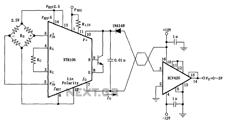
The IN4148 series diode is connected in the V+ line and configured in a loop to prevent damage from reverse voltage conditions. The diode exhibits a forward voltage drop of approximately 0.7V, which affects the supply voltage. The circuit...

Phase noise is a critical performance parameter of frequency synthesizers for wireless applications. RF system designers of phase-modulated cellular systems, such as PHS, GSM, and IS-54, require low noise local oscillator (L.O.) or frequency synthesizer blocks. This document describes...
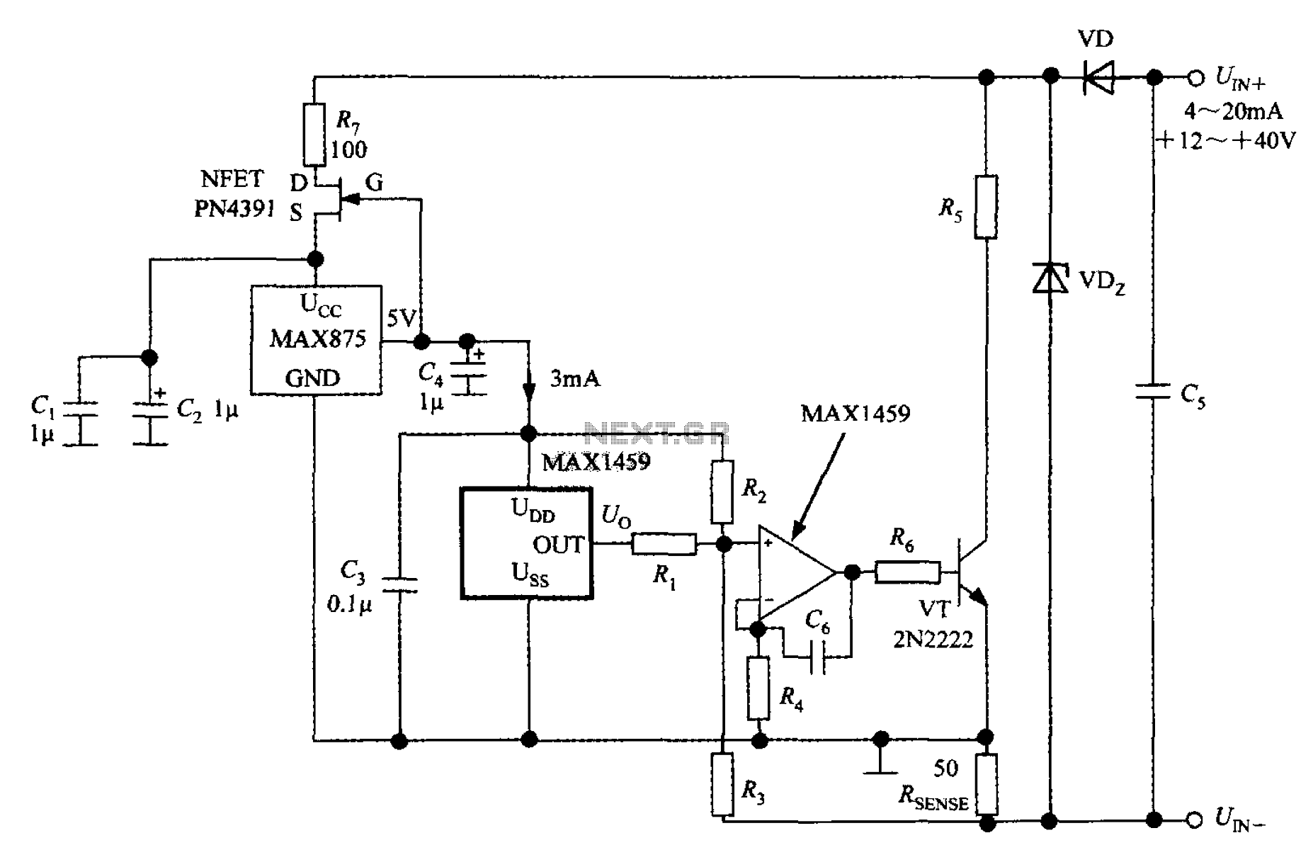
A 4 to 20 mA current transmitter circuit is implemented using the MAX1459, as illustrated in the accompanying figure. The output voltage from the programmable gain amplifier (PGA) is supplied to a spare amplifier chip, and subsequently, an external...
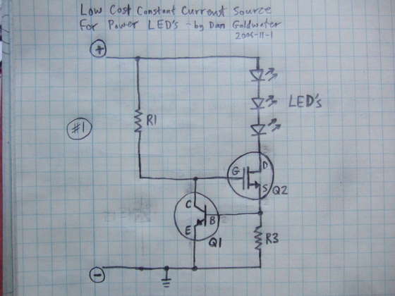
Here is a simple and cost-effective Power LED driver circuit. This power LED driver circuit is designed to efficiently drive high-power LEDs with a stable output. The circuit typically consists of a few key components: a power supply, a current...
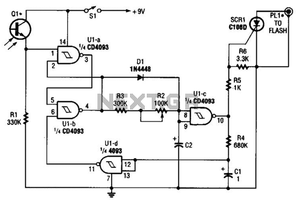
The circuit is built around a single 4093 quad 2-input NAND Schmitt trigger. Two gates from that quad package (U1-a and U1-b) are configured as a set-reset flip-flop. The 4093 integrated circuit (IC) contains four independent 2-input NAND gates with...
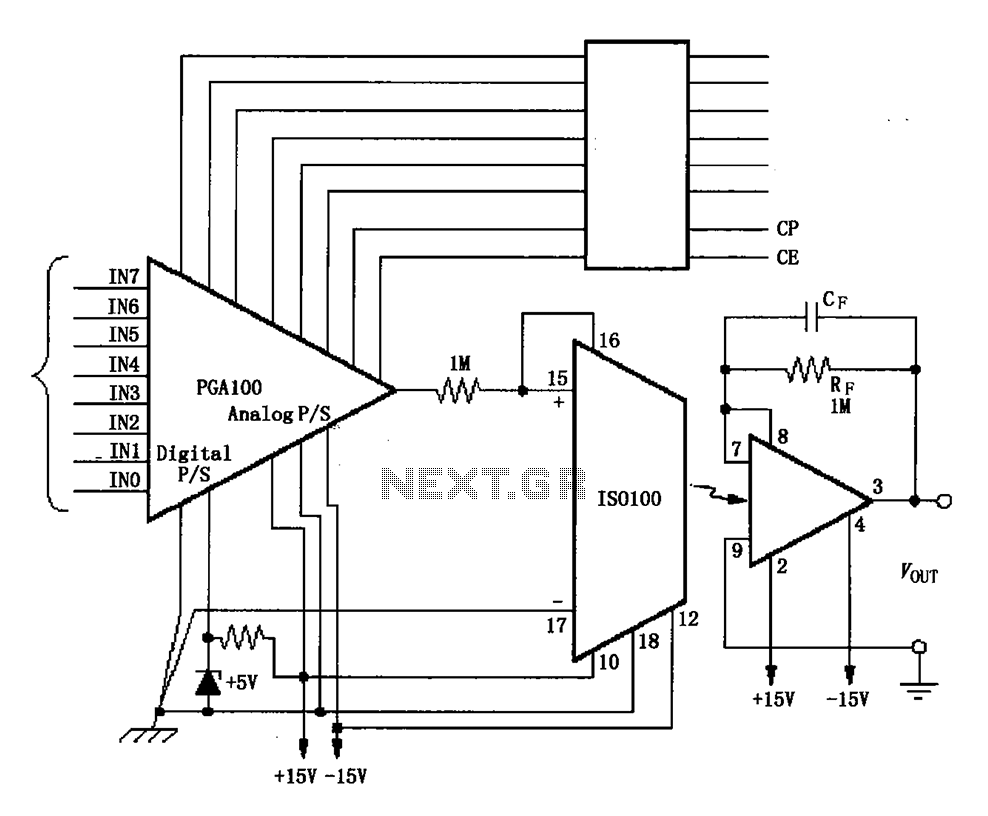
The ISO100 multichannel data acquisition system comprises a programmable gain amplifier isolated by an optocoupler, a programmable amplifier (PGA100), and an isolation amplifier (ISO100). The optocoupler selects three channels and is coupled to the programmable gain amplifier, which can...